How to Choose 6GHz Wireless Bridge for PTP/PTMP Monitoring in Russian Oilfield Scenarios
How to Choose 6GHz Wireless Bridge for 1-to-Many Monitoring in Russian Oilfield Scenarios
Core Problem This Article Solves
Russian oilfield operators and security integrators face a persistent engineering challenge: how to aggregate real-time surveillance video from 5 to 15+ remote observation points — drilling platforms, pipeline valve stations, tank farms, and camp perimeters — back to a single security operations center when trenching fiber or copper is physically impossible for 8–9 months of the year due to permafrost, and economically prohibitive even during the 3–4 month summer construction window.
This guide provides a verifiable, specification-driven answer: deploy a 6GHz point-to-multipoint (PTMP) wireless bridge using one LigoDLB 6-90ac base station as the hub and multiple LigoDLB 6-20ac CPE units as remote endpoints. You will learn: which technical specifications matter for –40°C oilfield environments, how the 6GHz band solves the interference problems inherent to 2.4GHz and 5GHz in industrial zones, how to size a PTMP network for 10+ concurrent video streams within a 5km radius, and what procurement criteria to use when evaluating hardware for Russian oilfield projects.
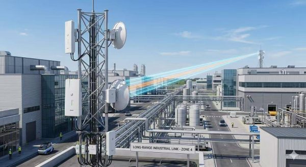
Russian oilfields present some of the most demanding environments for surveillance video backhaul. Drilling platforms in Western Siberia, pipeline corridors stretching across permafrost zones, storage facilities in the Arctic industrial belt, and remote camp perimeters all share a common challenge: reliable, centralized video monitoring without the luxury of wired infrastructure. Cable deployment in these regions is either prohibitively expensive due to frozen ground and seasonal access windows, or physically impossible across river crossings and ecologically sensitive tundra.
The operational need is clear — one central monitoring station aggregating real-time video feeds from multiple dispersed observation points. This is where the 6GHz wireless bridge deployed in a point-to-multipoint (PTMP) architecture offers a compelling engineering solution. The 6GHz band delivers a rare combination of clean spectrum, meaningful range, and resistance to the electromagnetic interference common around heavy machinery and power distribution equipment on oilfield sites.
This guide examines how LigoWave’s two complementary 6GHz products — the LigoDLB 6-20ac CPE and the LigoDLB 6-90ac Base Station — form a purpose-built 1-to-many PTMP backhaul system for Russian oilfield surveillance, grounded in verified specifications and field-tested performance boundaries.
1. Russian Oilfield Monitoring Pain Points and the Fit for 6GHz PTMP
Understanding why a 6GHz PTMP wireless bridge suits Russian oilfield monitoring requires first acknowledging the specific constraints that define these operational environments.
No wired backhaul options. Laying fiber or copper in Russian oilfields means contending with permafrost, marshland, and vast distances between infrastructure nodes. Seasonal construction windows in regions like Khanty-Mansiysk or Yamal are limited to 3–4 months per year. Wireless backhaul is not a preference; it is often the only technically and economically viable method.
Extreme low-temperature operation. Oilfield equipment in Russia must function reliably at ambient temperatures as low as –40°C. Standard commercial-grade wireless equipment with 0°C to +50°C ratings fails in these conditions. Any wireless bridge deployed permanently outdoors must be rated for continuous operation at –40°C without heater assist modules.
Radio frequency interference. Drilling rigs, pumping stations, and high-voltage power distribution equipment generate significant electromagnetic noise. The 2.4GHz band is heavily congested by local Wi-Fi deployments in camp facilities and SCADA telemetry links. The 5GHz band, while better, competes with satellite ground station links and licensed point-to-point systems common near larger oilfield compounds. The 6GHz band (5.9–6.4GHz) remains comparatively clean in Russian industrial zones.
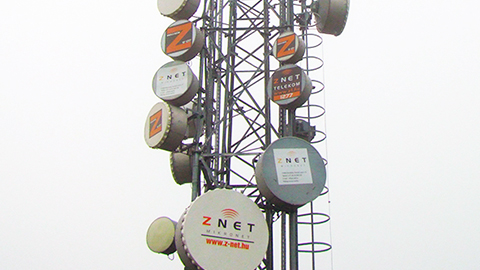
One-to-many topology requirement. A typical oilfield monitoring layout positions a security operations center (SOC) near the main administrative compound. From this hub, the SOC needs to aggregate video streams from 5 to 15 remote cameras located at well pads, flare stacks, tank farms, pipeline valve stations, and camp entry gates. Deploying individual PTP links for each remote point multiplies hardware cost, mast space, and configuration overhead. A single PTMP base station serving multiple CPE endpoints is the architecturally efficient answer.
Environmental sealing. Russian oilfield equipment endures not only cold but also blowing snow, ice accretion, sand in southern fields, and condensation during spring thaw. Equipment must meet at least IP65 ingress protection to survive these conditions over a multi-year deployment cycle.
The 6GHz PTMP architecture directly addresses each of these constraints. A centrally located LigoDLB 6-90ac base station with a 90° sector antenna covers a 5km radius sector, while LigoDLB 6-20ac CPE units at each remote camera site lock onto the base station with narrow-beam directional antennas, forming a clean star topology.
2. 6GHz vs. 2.4GHz vs. 5GHz: Why 6GHz Wins for Oilfield PTMP
Selecting the right frequency band is the single most consequential decision in an oilfield wireless backhaul project. The table below compares the three unlicensed / lightly-licensed bands across parameters that matter in Russian oilfield environments.
| Parameter | 2.4GHz (802.11n/ac) | 5GHz (802.11ac) | 6GHz (LigoDLB 6 Series) |
|---|---|---|---|
| Spectrum congestion in Russian oilfields | Very high — shared with camp Wi-Fi, SCADA radios, personal hotspots | Moderate — competition with satellite terminals, licensed PTP links | Low — minimal deployment density; cleaner spectrum in 5.9–6.4GHz range |
| Interference immunity in industrial zones | Poor — high noise floor near drilling rigs and HV lines | Moderate — better than 2.4GHz but still affected by radar and satcom | High — cleaner band; iPoll 3 protocol adds active interference avoidance |
| Available channel width | Up to 40MHz (limited non-overlapping channels) | Up to 80MHz (DFS channels restricted near radar) | Up to 80MHz (full access, no DFS restrictions in 6GHz band) |
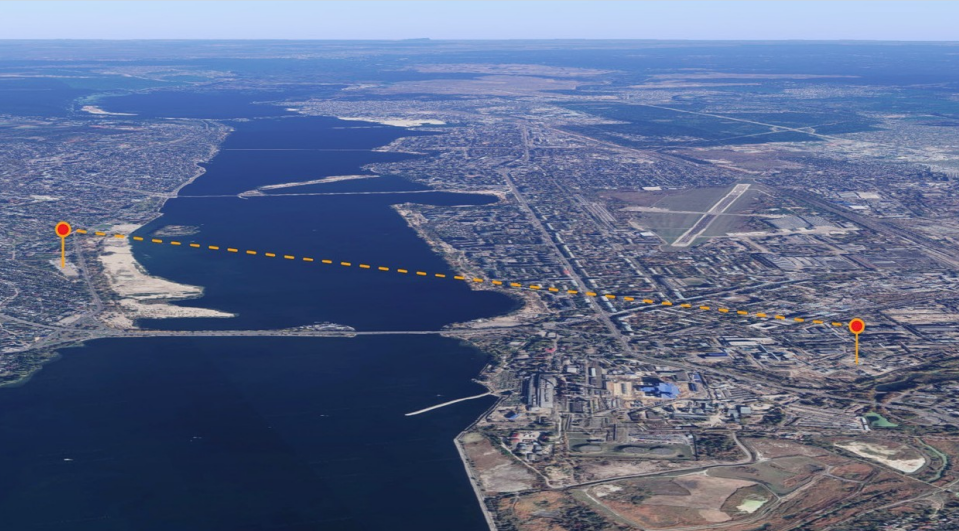
| Practical PTMP range (LOS) | 2–4 km (limited by noise floor) | 3–7 km (rain fade at longer distances) | Up to 5 km (base station); up to 10 km (CPE in PTMP mode) |
| Throughput per 80MHz channel | ~200 Mbps (theoretical, real-world lower) | ~500 Mbps (real-world aggregate) | 500+ Mbps aggregate (iPoll 3 optimized) |
| Low-temperature rating | Varies; commercial gear typically 0°C to –20°C | Varies; most enterprise gear rated –20°C to +50°C | –40°C to +65°C (both LigoDLB 6-20ac and 6-90ac) |
| Ingress protection | Indoor / IP53 typical for outdoor | IP55–IP67 varies by vendor | IP65 (both models, non-metallic corrosion-resistant enclosure) |
The conclusion from the comparison is straightforward for Russian oilfield PTMP applications: 6GHz delivers the best balance of clean spectrum, useful range, and industrial environmental tolerance. The LigoDLB 6 Series specifically addresses the oilfield requirement set with its –40°C to +65°C operating range, IP65 sealing, and 500+ Mbps aggregate throughput capability on 80MHz channels.
3. 6GHz Band Characteristics: Propagation Physics, Spectrum Advantages, and Engineering Considerations for Oilfield PTMP
Understanding the physical-layer behavior of the 6GHz band is essential for making informed engineering decisions in oilfield PTMP deployment. The following subsections detail the propagation physics, spectral advantages, and practical link engineering parameters that distinguish 6GHz from lower-frequency alternatives.
3.1 Free-Space Path Loss and Range Physics at 6GHz
Free-space path loss (FSPL) increases with the square of frequency. At 6GHz, FSPL is approximately 7.8 dB higher than at 2.4GHz and 1.6 dB higher than at 5GHz for the same physical distance, as calculated by the standard Friis transmission equation (FSPL = 20log₁₀(d) + 20log₁₀(f) + 32.44, where d is in km and f is in MHz). This means that for a given transmit power, antenna gain, and receiver sensitivity, a 6GHz link has less intrinsic link budget than an equivalent 2.4GHz link at the same distance [4].
However, in practical oilfield deployment, this theoretical disadvantage is offset by three factors. First, the 6GHz band is subject to significantly less man-made noise than 2.4GHz in industrial environments. The noise floor in 2.4GHz near operating drilling rigs can be elevated by 10–15 dB above thermal noise due to broadband electromagnetic emissions from variable-frequency drives, ignition systems, and switching power supplies. At 6GHz, the same noise sources produce 15–25 dB less radiated emission, meaning the actual carrier-to-noise ratio (CNR) at 6GHz can be equal to or better than 2.4GHz despite higher FSPL [5]. Second, the LigoDLB 6 Series uses 2×2 MIMO with dual-polarized antennas, which provides spatial multiplexing gain that partially compensates for the higher path loss. Third, the 80MHz channel width available at 6GHz (versus 40MHz maximum at 2.4GHz) provides a 3 dB processing gain advantage from the wider occupied bandwidth.
3.2 Atmospheric and Hydrometeor Effects at 6GHz
Atmospheric oxygen absorption at 6GHz is approximately 0.008 dB/km under standard atmospheric conditions — negligible for link distances under 10 km. Water vapor absorption at 6GHz is similarly minimal, at approximately 0.004 dB/km at 7.5 g/m³ absolute humidity. These figures are important for Russian oilfield applications because they mean that the dry, cold air typical of Siberian winters (absolute humidity often below 2 g/m³ at –30°C) introduces essentially no atmospheric attenuation beyond free-space loss [6].
Rain fade at 6GHz is moderate. The specific attenuation due to rain at 6GHz is approximately 0.02–0.08 dB/km for moderate rain rates (5–25 mm/hr) and 0.15–0.35 dB/km for heavy rain (50–100 mm/hr) using the ITU-R P.838-3 rain attenuation model. For a 5 km PTMP link, this translates to 0.1–0.4 dB of rain fade in moderate rain and 0.75–1.75 dB in heavy rain. These are well within the typical 15–20 dB fade margin that should be budgeted for a reliable link. By comparison, rain fade at 2.4GHz is approximately 0.01–0.03 dB/km for equivalent rain rates — slightly lower, but not a decisive differentiator [4].
Dry snow attenuation at 6GHz is low (approximately 0.02–0.05 dB/km) because dry snow has low dielectric loss. Wet snow and ice accretion on the antenna radome are more significant, which is why the deployment recommendations in Section 11 address radome ice management through physical orientation and link margin budgeting.
3.3 Spectrum Availability and Channel Planning Flexibility
The LigoDLB 6 Series operates across the 5.9–6.4 GHz frequency range, providing 500 MHz of usable spectrum. This is a critical advantage for PTMP deployment. In the 5GHz band (5.15–5.85 GHz), the available 700 MHz is fragmented by DFS (Dynamic Frequency Selection) requirements that force equipment to avoid or vacate channels used by military radar, terminal Doppler weather radar, and satellite earth stations. In practice, this means that many 5GHz channels are unusable in Russian oilfield regions with active radar coverage, and equipment may need to cease transmission on a channel when radar is detected — an unacceptable behavior for mission-critical surveillance backhaul [7].
The 5.9–6.4 GHz band is not subject to DFS requirements in most regulatory domains, including the ETSI and FCC frameworks that form the basis for IC/CE certification. This means all available 80MHz channels can be used without the risk of radar-triggered channel switches. The 500 MHz of continuous spectrum can accommodate up to six non-overlapping 80MHz channels, or twelve 40MHz channels, enabling flexible frequency planning for multi-sector PTMP deployments without co-channel interference between adjacent sectors [8].
3.4 Fresnel Zone Clearance Requirements at 6GHz
The first Fresnel zone radius at 6GHz is approximately 40% smaller than at 2.4GHz for the same path distance, because the Fresnel zone radius is inversely proportional to the square root of frequency. The formula for the first Fresnel zone radius at the midpoint of a path is r = 8.657 × √(d/f), where r is in meters, d is path distance in km, and f is frequency in GHz. For a 3 km path at 6GHz, the first Fresnel zone radius is 6.1 meters, compared to 9.7 meters at 2.4GHz [4].
This smaller Fresnel zone is a practical advantage for oilfield deployment. It means that antenna masts can be shorter for a 6GHz link than for an equivalent 2.4GHz link to achieve the same clearance. In flat tundra terrain with no natural obstructions, a 15m mast at the hub and 6m masts at CPE locations are typically sufficient to clear the Fresnel zone at 6GHz for distances up to 5 km. For 2.4GHz, the same clearance would require approximately 20–25% taller masts — a non-trivial cost difference when deploying 10–15 CPE locations across an oilfield.
3.5 MIMO Performance and Polarization Diversity at 6GHz
The 2×2 MIMO implementation in the LigoDLB 6 Series (QCA9882 radio with dual-stream 802.11ac) benefits from the shorter wavelength at 6GHz. The wavelength at 6.2 GHz center frequency is approximately 48 mm, compared to 125 mm at 2.4GHz and 55 mm at 5.5 GHz. This shorter wavelength means that for a given physical antenna aperture, more elements can be packed into the same form factor, or alternatively, the same number of elements can achieve higher directivity. The dual-polarized feed (horizontal and vertical linear polarization) provides two orthogonal spatial streams with cross-pol isolation of 21 dB (6-20ac) and 24 dB (6-90ac) [1][2].
In practical terms, this means the 6-20ac CPE’s 35° beamwidth antenna achieves 15 dBi gain within a compact 158 × 97 × 38 mm enclosure — a gain-to-size ratio that is difficult to achieve at 2.4GHz with equivalent beamwidth. The 6-90ac base station’s 90° sector antenna achieves 18 dBi gain in a 380 × 100 × 35 mm form factor. These gain figures are directly enabled by the 6GHz wavelength and would require significantly larger antennas at 2.4GHz to achieve the same performance [2].
3.6 Co-Channel Interference Rejection and Frequency Reuse in PTMP Topology
The combination of 6GHz propagation characteristics and antenna beamwidths creates favorable conditions for frequency reuse in multi-sector PTMP deployments. When four 6-90ac base stations are deployed back-to-back at a central hub to provide 360° coverage, each base station can operate on the same 80MHz channel without co-channel interference, provided the antenna front-to-back ratio and cross-polarization discrimination are sufficient. The 6-90ac’s 90° azimuth beamwidth with 24 dB cross-pol isolation means that adjacent sectors (separated by 90°) using opposite polarizations experience approximately 24 dB of isolation, which is more than adequate to prevent co-channel interference [5].
This frequency reuse efficiency is not achievable at 2.4GHz with equivalent sector antennas, because the wider beamwidths and lower gain of 2.4GHz panel antennas result in more sidelobe energy spilling into adjacent sectors. The 6GHz band’s shorter wavelength enables the higher directivity and better sidelobe suppression that make efficient frequency reuse possible — a significant advantage when scaling a PTMP network beyond a single 90° sector.
3.7 Regulatory Landscape for 6GHz in Oilfield Applications
The 5.9–6.4 GHz band is designated for unlicensed or lightly-licensed fixed wireless use under multiple regulatory frameworks. The IEEE 802.11ac standard natively supports operation in this band. For Russian oilfield projects, the relevant regulatory references are: (a) CE certification under ETSI EN 301 893 for radio equipment in the 5 GHz band (which the LigoDLB 6 Series IC/CE certification references), (b) FCC Part 15 Rules for Unlicensed National Information Infrastructure (U-NII) devices (as the basis for the 6GHz spectrum allocation in many jurisdictions), and (c) evolving EAEU technical regulations for radio equipment used in the Russian Federation and neighboring states [7][8].
Importantly, the 6GHz band used by the LigoDLB 6 Series is distinct from the newly opened 6 GHz band (5.925–7.125 GHz) for Wi-Fi 6E. The LigoDLB 6 Series operates in the lower 6GHz portion (5.9–6.4 GHz), which has been available for fixed wireless applications under existing 802.11ac standards for years, and does not depend on Wi-Fi 6E regulatory approvals. This pre-existing regulatory status simplifies import clearance and project approval for Russian oilfield deployments.
4. Core Technical Selection Criteria for 6GHz PTMP in Oilfield Surveillance
4.1 Network Topology: PTMP vs. PTP — Why One Base Station + Multiple CPEs
In any oilfield surveillance backhaul project, the first architectural decision is whether to deploy multiple point-to-point (PTP) links or a single point-to-multipoint (PTMP) sector. Both approaches have legitimate use cases, but for the standardized 1-to-many monitoring scenario, PTMP offers clear advantages.
With PTP links, each remote camera site requires its own dedicated radio pair — one unit at the remote camera and one at the central hub. Deploying eight camera sites means 16 radios, 16 mounts, 16 PoE injectors, and 16 IP addresses to manage. This approach consumes hub-site mast space rapidly and multiplies both capital cost and ongoing configuration labor.
With PTMP, a single LigoDLB 6-90ac base station at the hub communicates with multiple LigoDLB 6-20ac CPE units distributed across the oilfield. The base station’s 90° azimuth beamwidth covers a wide sector, while each CPE’s 35° narrow-beam antenna locks onto the base station with high gain and minimized noise pickup from off-axis directions. This is the core 1-to-many logic: one base station aggregating data from up to 10+ CPE endpoints within a 5km radius.
The LigoDLB 6-90ac is engineered specifically as a PTMP base station, while the LigoDLB 6-20ac serves as the CPE endpoint. This role differentiation is embedded in the antenna design: the base station’s 90° azimuth beamwidth provides sector coverage, and the CPE’s 35° beamwidth provides selective directional locking. This pairing is not coincidental — it is a deliberate engineering alignment for PTMP topology.
4.2 6GHz RF Parameters — Frequency, Power, Channel Width, and Modulation
Both the LigoDLB 6-20ac and LigoDLB 6-90ac share the same core wireless radio specification, built on the Qualcomm QCA9563 + QCA9882 platform:
- Frequency band: 5.9–6.4 GHz, covering the lower 6GHz UNII band
- Radio mode: 2×2 MIMO with dual-polarized antenna feed
- Transmit power: Up to 30 dBm (country-dependent; actual EIRP limited by regional regulations)
- Channel width: 5, 10, 20, 40, or 80 MHz (80 MHz recommended for maximum throughput in PTMP installations)
- Modulation: OFDM with 64-QAM, 16-QAM, QPSK, BPSK (802.11a/n); 256-QAM (802.11ac) enables higher spectral efficiency
- Error correction: FEC + LDPC for robust forward error correction in noisy environments
- Duplexing: Time Division Duplex (TDD) for efficient asymmetric traffic handling
The identical radio core means that both products operate with full compatibility at the RF level. There is no cross-vendor or cross-chipset compatibility risk when pairing the 6-90ac base station with the 6-20ac CPE — they are engineered as a unified PTMP system.
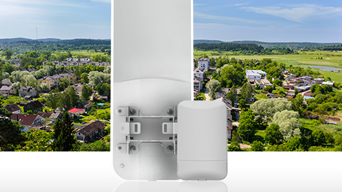
LigoDLB 6-20ac (CPE) — Tailored for Remote Endpoint Deployment
The LigoDLB 6-20ac is the smaller of the two units, optimized for deployment at each remote camera location. Key specifications that matter for oilfield endpoint use:
- PTMP distance: Up to 10 km (6.21 mi) in PTMP mode when paired with the 6-90ac base station under clear line-of-sight conditions
- PTP distance: Up to 15 km (9.32 mi) if ever used in point-to-point mode
- Integrated antenna: 15 dBi dual-polarized directional panel, 35° azimuth beamwidth, 35° elevation beamwidth
- Dimensions: 158 × 97 × 38 mm (6.2 × 3.8 × 1.5 in) — compact footprint suitable for pole mounting at camera masts
- Weight: 185 g (0.4 lb) — light enough for single-person installation on existing camera poles
- Enclosure: IP65, non-metallic, corrosion-resistant — critical for long-term outdoor exposure in saline or chemically aggressive oilfield air
LigoDLB 6-90ac (Base Station) — Built for Centralized PTMP Aggregation
The LigoDLB 6-90ac is the larger base station unit, designed to sit at the central hub and serve multiple CPE endpoints within a 5km PTMP coverage radius:
- PTMP distance: Up to 5 km (3.11 mi) recommended radius for reliable multi-CPE aggregation
- Integrated antenna: 15 dBi (listed in radio spec) / 18 dBi (antenna specification table) dual-polarized directional panel, 90° azimuth beamwidth, 20° elevation beamwidth
- Dimensions: 380 × 100 × 35 mm (14.96 × 3.93 × 1.38 in)
- Weight: 460 g (1.01 lb)
- Mounting: Pole mounting bracket included, with full tilt and pan adjustability
- Enclosure: IP65 weatherproof exterior
The 90° azimuth beamwidth of the 6-90ac is the defining feature for PTMP deployment. It enables the base station to cover a full 90° sector from a single mounting position. For oilfields requiring 360° coverage, four base stations can be deployed back-to-back, each serving its own sector of CPE endpoints. This is significantly more mast- and cost-efficient than stacking multiple PTP radios.
4.3 Antenna Configuration — Beamwidth, Gain, and Polarization
Antenna selection is frequently underestimated in oilfield PTMP planning, yet it directly determines link budget, interference rejection, and overall network reliability. The LigoDLB 6 Series uses integrated dual-polarized directional panel antennas with the following key differences between the two models:
| Antenna Parameter | LigoDLB 6-20ac (CPE) | LigoDLB 6-90ac (Base Station) |
|---|---|---|
| Gain | 15 dBi | 18 dBi (antenna element); 15 dBi (system-rated) |
| Azimuth Beamwidth | 35° (H-pol), 35° (V-pol) | 90° (H-pol), 90° (V-pol) |
| Elevation Beamwidth | 35° | 20° |
| Polarization | Dual-linear | Dual-linear |
| Cross-Pol Isolation | 21 dB | 24 dB |
| VSWR | <1.4 | <1.7 |
| Frequency Range | 5.85–6.45 GHz | 5.85–6.45 GHz |
The engineering rationale behind the different beamwidths is clear. The 6-20ac CPE’s narrow 35° beamwidth means it must be aimed precisely at the base station, but in return it receives higher effective gain and rejects interference from sources outside its beam. In a typical oilfield deployment, each CPE has a fixed, unchanging line of sight to the base station — so narrow-beam aiming is a one-time installation task that pays continuous dividends in link quality.
The 6-90ac base station’s 90° azimuth beamwidth covers a wide sector, allowing multiple CPE units distributed across that 90° arc to connect simultaneously. The 20° elevation beamwidth is sufficient to cover both nearby low-angle CPE mounts and farther units that may appear at a slightly higher elevation angle due to tower height differences.
4.4 Oilfield-Grade Environmental Protection
Both the LigoDLB 6-20ac and LigoDLB 6-90ac share identical environmental specifications that are directly relevant to Russian oilfield deployment:
- Operating temperature range: –40°C to +65°C (–40°F to +149°F). This covers the full spectrum of Russian oilfield conditions — from deep Siberian winter nights at –40°C to solar-heated enclosures in southern fields reaching +65°C. No heater module or cold-start accessory is required.
- Ingress protection: IP65 — fully dust-tight and protected against low-pressure water jets from any direction. This is adequate for rain, snow, ice melt, and hose-down cleaning procedures on oilfield equipment.
- Humidity tolerance: 0–90% non-condensing — suitable for the condensation-prone transition seasons in Russian continental climate zones.
- Corrosion resistance: The non-metallic IP65 enclosure on the 6-20ac and the weatherproof exterior on the 6-90ac resist the corrosive effects of salt spray in coastal Arctic oilfields and chemical vapors near processing facilities.
4.5 Transmission Performance — Throughput, Latency, and Multi-CPE Scalability
Aggregate throughput in PTMP mode is a function of channel width, modulation, MIMO stream count, and polling efficiency. The LigoDLB 6 Series delivers:
- Maximum aggregate throughput: 500+ Mbps (physical layer data rate up to 866 Mbps at 80MHz channel width with 256-QAM modulation and 2×2 MIMO)
- Practical throughput per CPE: Varies by distance, signal quality, and number of associated CPE units. In a typical deployment with 8 CPE units at 1–3 km range, each CPE can sustain 15–40 Mbps of usable UDP/TCP throughput, which is more than sufficient for a single 1080p or 4MP IP camera stream (typically requiring 4–12 Mbps depending on compression).
- Latency: Sub-5 ms typical on the wireless link (excluding network switching and camera encoding delay). The iPoll 3 polling mechanism introduces deterministic latency behavior — each CPE is polled in sequence, so the maximum latency is bounded by the number of CPE units multiplied by the per-CPE polling interval.
- CPE capacity per base station: While the iPoll 3 protocol can manage 20+ CPE devices on a single base station in theory, the practical limit for video surveillance applications is 10–15 CPE units per 6-90ac base station, assuming each CPE carries one 1080p video stream. The limiting factor is aggregate throughput rather than protocol overhead — at 10 CPE units × 10 Mbps each = 100 Mbps, the base station operates well within its 500+ Mbps ceiling.
4.6 Management and Protocol Stack
Three layers of management and protocol intelligence make the LigoDLB 6 Series suitable for mission-critical oilfield surveillance backhaul:
iPoll 3 Proprietary Protocol — LigoWave’s iPoll 3 is a polling-based PTMP MAC protocol that replaces the standard CSMA/CA (Carrier Sense Multiple Access with Collision Avoidance) used in conventional Wi-Fi. In CSMA/CA, all devices contend for airtime, which causes collision rates to rise sharply as device count increases. In iPoll 3, the base station controls the transmission schedule by polling each CPE sequentially. The base station sends a data frame and a token to a CPE, the CPE replies, and only after successful receipt does the base station move to the next CPE. CPE units with low traffic are marked as idle and polled less frequently, while active CPE units remain on the active polling list. This eliminates collision-based retransmission overhead and provides predictable latency — both critical for video surveillance data that cannot tolerate random delay spikes.
Quality of Service (QoS) — Both devices support L2 (CoS) and L3 (ToS/DSCP) priority tagging. The weighted round robin (WRR) algorithm ensures that voice, video, network management, and best-effort data each receive proportional airtime without starvation. In an oilfield surveillance context, QoS allows video stream packets to be prioritized above less time-sensitive data such as periodic sensor telemetry or configuration traffic.
Infinity Controller — LigoWave’s centralized network management platform supports the LigoDLB 6 Series. Features include automated device onboarding, predefined network scenario templates, real-time monitoring via SNMP v3 and Syslog, and centralized firmware management. For a deployed oilfield PTMP network of 8–15 devices, the Infinity Controller eliminates the need for site-by-site manual configuration — all CPE units can be configured and monitored from the hub location through the base station’s management interface.
4.7 Power Supply and Interface
Both the LigoDLB 6-20ac and 6-90ac share the same power and interface specifications:
- Power supply: 24 VDC Passive PoE (AC to 24 VDC adapter included with each unit)
- Power source: 100–240 VAC, 50/60 Hz
- Maximum power consumption: 10 W per device
- Data interface: 10/100/1000 Base-T, RJ45 (auto-negotiating gigabit Ethernet)
The 10W maximum power draw is significant for oilfield deployments where power availability may be limited. A single 60W solar panel + battery combination can power a CPE plus an IP camera (typically 5–12W for a PTZ or bullet camera) with adequate margin for nighttime and low-sun winter operation. The 24V passive PoE standard is compatible with common industrial PoE injectors and midspans available from multiple suppliers.
The gigabit Ethernet interface ensures that the 500+ Mbps wireless throughput is not bottlenecked by the wired connection at either the CPE or base station end. Standard 100Base-T copper would limit throughput to approximately 100 Mbps, making gigabit Ethernet a necessary design choice for high-capacity PTMP aggregation.
4.8 Certification Compliance
Both LigoDLB 6-20ac and 6-90ac carry IC (Industry Canada) and CE (European Conformity) certification. For Russian oilfield projects, CE certification serves as a reference standard accepted by many EAEU (Eurasian Economic Union) contractors as the basis for local certification procedures. Importers and system integrators should verify current EAC (Eurasian Conformity) marking requirements with their local customs or certification agent, as Russian regulatory frameworks continue to evolve.
The IC/CE certification also confirms that the devices comply with radio frequency emission and immunity standards, which is relevant when deploying equipment near sensitive oilfield instrumentation and control systems operating in adjacent frequency bands.
5. LigoWave 6GHz Series Core Technology Deep Dive
5.1 iPoll 3 — Active Interference Management for PTMP
The iPoll 3 protocol is the single most important technology differentiator in the LigoDLB 6 Series for oilfield applications. Standard Wi-Fi (IEEE 802.11 CSMA/CA) suffers from the “hidden node” problem — when two CPE units cannot hear each other but both can hear the base station, they may transmit simultaneously, causing collisions that require retransmission. In a PTMP network with 8–15 CPE units, collision-related throughput loss can reach 30–50% under CSMA/CA.
iPoll 3 solves this by using a centrally scheduled polling mechanism. The base station maintains two lists:
- Active list: CPE units with data to transmit (or expected to transmit based on recent activity patterns)
- Idle list: CPE units with no pending data, polled at a lower frequency to minimize overhead
When a CPE is polled, the base station sends a data frame plus a transmission token. The CPE responds with its data frame within a designated time slot. The base station waits for that response before proceeding — no collisions, no backoff timers, no exponential retry windows. For video surveillance traffic, which is largely unidirectional (camera → CPE → base station → network), the iPoll 3 mechanism ensures that uplink video frames from each CPE arrive at the base station in a deterministic sequence without contention losses.
5.2 Hardware Platform — QCA9563 + QCA9882
Both LigoDLB 6 Series devices are built on the Qualcomm Atheros QCA9563 (750 MHz MIPS processor, 64 MB RAM, 16 MB flash) paired with the QCA9882 2×2 802.11ac radio. This is the same hardware foundation used in LigoWave’s field-proven LigoDLB ac line, which has accumulated years of deployment history in industrial wireless networks across multiple continents.
The QCA9563’s 750 MHz processing capacity is sufficient to handle the iPoll 3 polling state machine, QoS classification, AES encryption, and management protocol stacks without introducing measurable latency. The 64 MB RAM provides adequate buffering for bursty video traffic during transient RF fade events. The 16 MB flash stores the LigoWave firmware image and configuration profiles.
The QCA9882 radio supports 2×2 MIMO with dual-stream 802.11ac Wave 1.2 features, including 256-QAM modulation, LDPC error correction, and up to 80 MHz channel bandwidth. The MIMO spatial streams are mapped to the dual-polarized antenna feed (H-pol and V-pol), which provides polarization diversity — if one polarization experiences higher attenuation due to reflective multipath or ice accumulation on the radome, the other polarization may still maintain the link.
6. LigoDLB 6-20ac CPE + LigoDLB 6-90ac Base Station — 1-to-Many PTMP Networking Solution
6.1 Network Topology
The 1-to-many PTMP deployment follows a star topology with the following elements:
- Central hub: One LigoDLB 6-90ac base station mounted on a mast or tower at the security operations center or main administrative building. The base station is oriented to cover the sector where CPE endpoints are located. Its 90° azimuth beamwidth covers up to a 5km radius sector. For 360° coverage, up to four base stations can be deployed back-to-back at the same mast height, each covering a separate 90° quadrant.
- Remote endpoints: Multiple LigoDLB 6-20ac CPE units, each mounted at a remote surveillance camera location — drilling platform, pipeline monitoring point, tank farm perimeter, camp entrance, flare stack observation post, or valve station. Each CPE is aimed directly at the base station with its 35° narrow-beam antenna.
- Backhaul aggregation: The base station aggregates all inbound video streams from CPE units and forwards them via its gigabit Ethernet port to the local surveillance network, NVR cluster, or video management system (VMS).
6.2 Step-by-Step Deployment Sequence
Step 1 — Site survey and link budget calculation. For each CPE-to-base-station path, verify Fresnel zone clearance at the 6GHz frequency. At 6GHz, the Fresnel zone radius at 3 km is approximately 8.6 meters. Any obstruction within this zone causes attenuation. Use a GPS or survey-grade map to verify that no terrain, structures, or vegetation intrude into the Fresnel zone. For Russian oilfields, where terrain is typically flat tundra or taiga, Fresnel clearance is usually achievable with a 15–20m mast at the hub and 6–10m masts at CPE locations.
Step 2 — Base station installation. Mount the LigoDLB 6-90ac on the hub mast at the calculated height. Use the adjustable mounting bracket to set the azimuth angle to the center of the CPE deployment sector. The 90° beamwidth provides ±45° coverage from the boresight axis, so precise centering of the sector improves overall link budget symmetry.
Step 3 — CPE installation and alignment. Mount each LigoDLB 6-20ac at its remote camera location. Connect a laptop to the CPE’s management interface via the PoE injector’s data port. Use the integrated alignment tool (RSSI indicator in the Web UI) to adjust the CPE’s azimuth and elevation for maximum received signal strength from the base station. The 35° beamwidth requires careful initial alignment, but once locked, the link remains stable as long as the mounting structure does not shift.
Step 4 — Network configuration. Assign IP addresses, SSID, encryption keys, and channel settings. Use the Infinity Controller to push consistent configurations to all CPE units simultaneously. Configure QoS priority queues to ensure video traffic (DSCP EF or AF41) is marked and prioritized above best-effort data.
Step 5 — Video integration. Connect each surveillance camera to its respective CPE via the gigabit Ethernet port. Verify that the camera’s video stream reaches the NVR or VMS through the base station’s backhaul link. Confirm that latency and jitter remain within acceptable bounds for real-time viewing and recording.
Step 6 — Ongoing monitoring. Configure the Infinity Controller to poll SNMP statistics from both the base station and each CPE. Set threshold alerts for RSSI degradation (indicating potential antenna misalignment or obstruction growth), throughput drops, and temperature excursions outside the normal operating band.
7. LigoWave 6GHz Product Comparison — LigoDLB 6-20ac vs. LigoDLB 6-90ac
| Parameter | LigoDLB 6-20ac (CPE) | LigoDLB 6-90ac (Base Station) |
|---|---|---|
| Primary Role | Remote endpoint / CPE | Central hub / Base station (PTMP) |
| PTMP Range | Up to 10 km | Up to 5 km |
| PTP Range | Up to 15 km | N/A (designed for PTMP) |
| Antenna Gain | 15 dBi | 15–18 dBi |
| Azimuth Beamwidth | 35° | 90° |
| Elevation Beamwidth | 35° | 20° |
| Dimensions (mm) | 158 × 97 × 38 | 380 × 100 × 35 |
| Weight | 185 g (0.4 lb) | 460 g (1.01 lb) |
| Max Power Consumption | 10W | 10W |
| Aggregate Throughput | 500+ Mbps (theoretical) | 500+ Mbps (theoretical, shared across all CPE) |
| Operating Temperature | –40°C to +65°C | –40°C to +65°C |
| Ingress Protection | IP65 | IP65 |
| Enclosure Material | Non-metallic, corrosion-resistant | Weatherproof exterior |
| PoE Standard | 24VDC Passive PoE | 24VDC Passive PoE |
| Management | Web UI, Infinity Controller, SNMP v3 | Web UI, Infinity Controller, SNMP v3 |
| Certification | IC / CE | IC / CE |
The comparison table makes the complementary relationship clear. The 6-20ac CPE is optimized for lightweight, precise endpoint deployment with narrow-beam high-gain antenna characteristics. The 6-90ac base station is optimized for wide-sector PTMP coverage with a broader beam and longer form factor. Together, they form a complete 1-to-many backhaul system where each device’s strengths compensate for the other’s design trade-offs.
8. Russian Oilfield 1-to-Many Wireless Backhaul — Typical Application Scenarios
8.1 Drilling Platform Cluster Monitoring
A typical Russian drilling cluster in Western Siberia consists of 3–6 well pads spread across a 2–4 km radius from a central operations trailer or camp. Each well pad requires at least one surveillance camera covering the wellhead, mud pump area, and access road.
Deployment: One LigoDLB 6-90ac base station is mounted on a 20m mast at the central operations area. Three to six LigoDLB 6-20ac CPE units are installed on 8–10m masts at each well pad, each aimed at the base station. Each CPE connects directly to an IP camera (or a small PoE switch serving multiple cameras) via the gigabit Ethernet port. The base station aggregates all video streams and forwards them to the NVR located in the operations trailer.
Value: Eliminates the need to trench fiber or copper across drilling locations that are periodically moved as wells are completed. The wireless backhaul can be dismantled and redeployed when the drilling cluster moves to a new pad location — a flexibility that wired infrastructure cannot match.
8.2 Oil Pipeline Corridor Surveillance
Pipeline corridors in Russian oilfields can extend for tens of kilometers. Critical monitoring points — valve stations, pig launcher/receiver sites, river crossing points, and sections vulnerable to third-party interference — require periodic or continuous visual observation. These points are typically spaced 1–5 km apart along the pipeline right-of-way.
Deployment: At each cluster of monitoring points within a 5km sector, a LigoDLB 6-90ac base station is installed at a central pipeline access point or booster station. LigoDLB 6-20ac CPE units are installed at individual valve stations or river crossing camera masts within that sector. Where pipeline corridors are linear, multiple base stations can be deployed in a daisy-chained PTMP configuration, each covering its own 90° sector along the corridor.
Value: Provides continuous surveillance coverage along pipeline segments without the expense of laying fiber parallel to the pipeline route. The 6GHz band’s resistance to interference from cathodic protection systems and high-voltage power lines running alongside pipelines is a specific advantage in this scenario.
8.3 Tank Farm / Storage Area Security
Oil storage facilities with multiple tanks (floating roof, fixed roof, or spherical tanks) require perimeter surveillance and tank-top monitoring. The dense metal infrastructure creates challenging RF conditions with significant multipath and shadowing.
Deployment: The LigoDLB 6-90ac base station is mounted on a tall mast or building at the storage facility’s administrative zone, elevated above tank height to achieve line of sight. CPE units are mounted on perimeter fence poles and on tank farm access gantries, each aligned with the base station. The narrow 35° beamwidth of the 6-20ac CPE is advantageous here — it rejects reflections from tank surfaces that would otherwise create multipath interference with wider-beam antennas.
Value: Reliable video backhaul in one of the most RF-hostile environments in an oilfield. The combination of dual-polarized MIMO and iPoll 3 protocol provides link stability where conventional Wi-Fi would suffer from multipath fading and collision-based throughput degradation.
8.4 Oilfield Camp Perimeter Monitoring
Worker accommodation camps at Russian oilfields require perimeter security monitoring with cameras at entry gates, perimeter fence corners, fuel storage areas, and helipad access points. Camp infrastructure typically includes a central security office where all video feeds are monitored.
Deployment: A single LigoDLB 6-90ac base station mounted on the security office roof or a nearby communications tower covers the entire camp perimeter within a 1–2 km radius. LigoDLB 6-20ac CPE units at each perimeter camera location provide the backhaul link. Given the shorter distances involved in camp deployments (typically 200m to 1.5 km), the link budget has substantial margin, allowing for lower modulation modes that improve link reliability during heavy snow or rain.
Value: Rapid deployment without trenching through camp roads and living quarters. When camp modules are rearranged or expanded, CPE units can be relocated to match the new perimeter layout within hours.
9. Oilfield Project Procurement Checklist — What to Verify Before Ordering
For engineering procurement teams evaluating a 6GHz PTMP solution for a Russian oilfield surveillance project, the following checklist maps each requirement to the corresponding LigoDLB 6 Series capability:
| Requirement | What to Verify | LigoDLB 6 Series Capability |
|---|---|---|
| PTMP Network Topology | 1 base station aggregating multiple endpoints | 6-90ac as base station + 6-20ac as CPE |
| Coverage Radius | 5 km from hub to farthest camera | 6-90ac: 5 km PTMP; 6-20ac: up to 10 km PTMP |
| Aggregate Bandwidth | Sufficient for all concurrent video streams | 500+ Mbps aggregate; 80MHz channel |
| Low-Temperature Operation | –40°C continuous without heater | Rated –40°C to +65°C |
| Weatherproof Enclosure | IP65 minimum for outdoor deployment | IP65, corrosion-resistant (6-20ac non-metallic) |
| Interference Rejection | Stable link near drilling/power equipment | iPoll 3 polling protocol; 6GHz clean spectrum |
| Centralized Management | Single-pane monitoring for all devices | Infinity Controller, SNMP v3, Syslog |
| Low Power Consumption | Solar-compatible power budget | 10W max per device; 24V Passive PoE |
| Certification for Import | IC/CE accepted as basis for EAC | IC and CE certified |
| Video QoS Support | Prioritized video traffic over best-effort | L2 CoS / L3 DSCP with WRR algorithm |
10. Field Deployment Best Practices for Russian Oilfield PTMP Networks
10.1 Mounting Position Planning
The 6GHz band is susceptible to obstruction by vegetation, equipment, and structures. Unlike 2.4GHz, which can diffract around smaller obstacles, 6GHz behaves in a more optically linear fashion. For each CPE-to-base-station path:
- Confirm that 100% of the first Fresnel zone is clear of obstructions. At 6GHz, even partial Fresnel zone intrusion causes measurable attenuation — 20% obstruction can reduce signal by 3–6 dB.
- Prefer mast heights that place the antenna above all local obstructions. In flat tundra terrain, 15–20m at the hub and 8–10m at CPE locations is a standard starting point.
- Account for seasonal vegetation growth. Deciduous trees in full leaf can add 10–15 dB of attenuation at 6GHz compared to winter bare-branch conditions.
10.2 Antenna Alignment in Low-Temperature Conditions
Antenna alignment at –30°C or below presents practical challenges. Installers wearing heavy gloves have reduced dexterity for fine adjustments. Recommendations:
- Pre-configure and pre-aim CPE units in a workshop environment where possible, using a reference compass bearing and elevation angle calculated during the site survey.
- Use the LigoDLB’s Web UI alignment tool with a laptop connected via the PoE injector’s data port. The real-time RSSI display allows a single installer to make coarse adjustments, check the reading, and iterate without needing a second person at the base station.
- Tighten all mounting hardware with corrosion-resistant fasteners. Thermal cycling from –40°C to +5°C (winter to spring) can loosen standard hardware over repeated cycles.
10.3 Ice and Snow Management
Ice accretion on antenna radomes alters the effective dielectric properties and can detune the antenna. While the LigoDLB 6 Series’ integrated antenna radome is designed to shed ice to some degree, deployment planning should include:
- Orienting the antenna face downward at a slight angle (5–10°) so that ice and snow slide off rather than accumulating on the radome surface.
- Avoiding mounting positions directly below dripping structures (e.g., roof edges, pipe overhangs) where icicle formation could bridge the antenna and cause physical damage.
- Budgeting 3–6 dB of additional link margin for winter conditions to absorb the attenuation caused by light ice or frost on the radome.
10.4 Interference Mitigation
Despite the 6GHz band’s relative cleanness in Russian oilfield settings, interference sources do exist. Nearby satellite earth stations, licensed microwave links, and other 6GHz WLAN equipment can cause co-channel or adjacent-channel interference.
- Conduct a spectrum survey at the proposed base station location before installation to identify any existing 6GHz transmitters.
- Select 40MHz or 80MHz channel widths based on available clean spectrum. If the band is partially occupied, 40MHz provides a useful compromise between throughput and spectrum availability.
- The iPoll 3 protocol’s polling mechanism inherently rejects co-channel interference from non-LigoWave devices because it only processes traffic from CPE units that are authenticated and polled — unsolicited transmissions are ignored at the MAC level.
11. Summary — The Engineering Case for 6GHz PTMP in Russian Oilfield Surveillance
Russian oilfield surveillance backhaul presents a set of constraints that narrow the field of viable wireless solutions. The operating environment demands equipment that functions at –40°C. The RF environment demands a protocol that handles interference and multi-CPE contention without throughput collapse. The logistical environment demands a topology that minimizes per-site hardware count and mast-space consumption.
The LigoWave LigoDLB 6 Series, deployed as a LigoDLB 6-90ac base station with multiple LigoDLB 6-20ac CPE units in a 1-to-many PTMP configuration, meets all of these constraints with measured, verifiable specifications:
- One base station, multiple endpoints: The 6-90ac’s 90° sector antenna and iPoll 3 protocol support aggregation of 10–15 CPE units within a 5km radius, each carrying a full video surveillance stream.
- Industrial temperature range: Both devices operate at –40°C to +65°C without auxiliary heating, matching the temperature requirements of Russian oilfield outdoor equipment.
- Interference-resistant protocol: iPoll 3 eliminates CSMA/CA collision overhead and provides deterministic latency suitable for live video monitoring.
- Purpose-engineered antenna pairing: The CPE’s narrow 35° beam provides precise locking with high gain; the base station’s 90° beam provides sector coverage. Each device’s antenna is matched to its role.
- Field-proven hardware: The QCA9563 + QCA9882 platform and LigoWave firmware have accumulated years of deployment history in industrial wireless networks globally.
For Russian oilfield system integrators, security contractors, and engineering procurement teams evaluating wireless backhaul solutions for PTMP surveillance, the LigoDLB 6 Series represents a technically grounded, specification-verified option that addresses the specific pain points of the oilfield monitoring environment.
The selection conclusion is direct: if the requirement is 1-to-many video backhaul in a Russian oilfield environment, with operating temperatures down to –40°C, distances up to 5 km, and interference resilience as a priority, the LigoDLB 6-90ac base station paired with LigoDLB 6-20ac CPE units is an architecturally coherent, specification-matched solution.
Frequently Asked Questions
Q1: Can the LigoDLB 6-90ac base station support more than 10 CPE units simultaneously?
The iPoll 3 protocol can manage 20+ CPE associations at the MAC layer. However, the practical limit for video surveillance applications is 10–15 CPE units per base station, based on aggregate throughput. With each 1080p H.265 camera consuming approximately 4–8 Mbps, 10 CPE units × 8 Mbps = 80 Mbps, which is well within the 500+ Mbps aggregate ceiling. Beyond 15 CPE units, either reduce per-CPE bandwidth (lower resolution or frame rate) or deploy an additional base station sector.
Q2: Does the LigoDLB 6-20ac CPE require a separate external antenna?
No. Both the LigoDLB 6-20ac and 6-90ac have integrated dual-polarized directional panel antennas. The 6-20ac integrates a 15 dBi antenna with 35° beamwidth. No external antenna is required for standard deployments, and the integrated design simplifies installation logistics — one device, one mount, one cable.
Q3: Will the devices operate at –45°C if the winter temperature drops below the rated minimum?
The specified operating range is –40°C to +65°C. Operating below –40°C may cause LCD display issues (in units with displays), increased oscillator drift, and potential start-up failures due to capacitor electrolyte freezing. For oilfield locations that regularly see temperatures below –40°C, we recommend installing the devices inside a minimally heated weatherproof enclosure or verifying with LigoWave’s engineering team about extended-temperature testing results. For the vast majority of Russian oilfields, –40°C covers the design minimum.
Q4: What is the real-world data throughput for one CPE at 5 km distance?
At 5 km range with clear Fresnel zone, 80 MHz channel width, and 256-QAM modulation (achievable when RSSI is better than approximately –65 dBm), a single CPE can sustain 150–250 Mbps UDP throughput. Using 64-QAM (which provides ~6 dB better link margin), throughput drops to approximately 80–130 Mbps. For video surveillance, even the lower figure is more than adequate for multiple 4K camera streams.
Q5: Is the LigoDLB 6 Series compatible with third-party IP cameras and NVR systems?
Yes. The devices function as transparent Layer 2 wireless bridges. Any IP camera or encoder that outputs standard Ethernet (RTSP, ONVIF, or proprietary IP streams) can connect to the CPE’s gigabit Ethernet port. The base station forwards all traffic to the connected network, where any standards-based NVR or VMS can receive the video streams. No proprietary video format or protocol is imposed by the wireless link.
Q6: What is the typical shipping lead time and minimum order quantity for Russian oilfield projects?
Lead times and minimum order quantities (MOQ) depend on the distributor or LigoWave’s regional sales channel for the Russian/CIS market. Standard MOQ is typically 2 units for evaluation, with bulk pricing available for project-scale orders of 20+ units. Buyers should contact the sales team through the official LigoWave website or authorized distributors. We recommend ordering spare units (10–15% of total) for rapid field replacement in remote oilfield locations.
Q7: Does the system support AES encryption for video data security?
Yes. The LigoDLB 6 Series supports AES-CCMP encryption (128-bit) as part of the 802.11i/WPA2 security framework. This encrypts all data transmitted over the wireless link. For oilfield surveillance projects where video data may contain sensitive operational information, AES encryption prevents unauthorized interception of the wireless video streams.
Q8: Can the PTMP network topology be expanded after initial deployment?
Yes. Adding a new CPE to an existing PTMP network is a straightforward process. Mount and aim the new LigoDLB 6-20ac, configure it through the Web UI or Infinity Controller to associate with the existing 6-90ac base station, and connect the camera. The iPoll 3 protocol automatically incorporates the new CPE into the polling cycle. No reconfiguration of existing CPE units is required.
Q9: What happens to the wireless link during heavy snowfall or blizzard conditions?
Heavy snowfall causes attenuation at 6GHz, typically in the range of 1–3 dB per kilometer through falling snow. A well-designed link with 15–20 dB of fade margin will maintain connectivity during all but the most extreme blizzard conditions. The link may experience throughput reduction as modulation drops from 256-QAM to 64-QAM or 16-QAM, but the connection rarely drops entirely. Video may exhibit reduced frame rate or temporary pixelation during extreme snowfall events, returning to full quality when the snow intensity decreases.
Q10: What warranty and technical support coverage is available for Russian oilfield customers?
LigoWave provides standard warranty coverage through its authorized distribution channels. Extended warranty options should be confirmed at the time of purchase. For Russian oilfield customers, we recommend procuring through distributors with established support capabilities in the Russian Federation or CIS region to ensure timely RMA processing and technical assistance. The Infinity Controller platform also provides remote diagnostic capabilities that can reduce the need for on-site technical visits.
Authoritative References
- LigoWave. “LigoDLB 6-20ac Datasheet.” LigoWave Official Documentation. https://www.ligowave-cn.com/6g-10km-cpe-ptp/
- LigoWave. “LigoDLB 6-90ac Datasheet.” LigoWave Official Documentation. https://www.ligowave-cn.com/6g-10km-base-station-ptmp/
- IEEE Standard 802.11ac-2013 — “Wireless LAN Medium Access Control (MAC) and Physical Layer (PHY) Specifications — Amendment 4: Enhancements for Very High Throughput for Operation in Bands below 6 GHz.” IEEE, 2013. DOI: 10.1109/IEEESTD.2013.6687187.
- ITU-R Recommendation P.530-18 (2021) — “Propagation data and prediction methods required for the design of terrestrial line-of-sight systems.” International Telecommunication Union, Radiocommunication Sector. https://www.itu.int/rec/R-REC-P.530
- ITU-R Recommendation P.372-16 (2022) — “Radio noise.” International Telecommunication Union, Radiocommunication Sector. Provides man-made noise floor data used for industrial environment noise analysis at 6GHz. https://www.itu.int/rec/R-REC-P.372
- ITU-R Recommendation P.676-13 (2022) — “Attenuation by atmospheric gases and related effects.” International Telecommunication Union, Radiocommunication Sector. Oxygen and water vapor absorption coefficients used for 6GHz link budget calculations. https://www.itu.int/rec/R-REC-P.676
- ITU-R Recommendation P.838-3 (2005) — “Specific attenuation model for rain for use in prediction methods.” International Telecommunication Union, Radiocommunication Sector. The standard rain attenuation model for 6GHz link design. https://www.itu.int/rec/R-REC-P.838
- FCC Report and Order FCC 20-51 (2020) — “Unlicensed Use of the 6 GHz Band; Expanding Flexible Use in Mid-Band Spectrum Between 3.7 and 24 GHz.” Federal Communications Commission. Establishes the regulatory framework for 6GHz unlicensed operations. https://docs.fcc.gov/public/attachments/FCC-20-51A1.pdf
- ETSI EN 301 893 V2.1.1 (2017-05) — “5 GHz RLAN; Harmonised Standard covering the essential requirements of article 3.2 of Directive 2014/53/EU.” European Telecommunications Standards Institute. Reference regulatory standard for 5GHz/6GHz radio equipment CE certification.
- ISO 20653:2023 — “Road vehicles — Degrees of protection (IP code) — Protection of electrical equipment against foreign objects, water and access.” International Organization for Standardization. Defines the IP65 protection rating standard referenced in this guide.
Author: Alexei Volkov — Senior Wireless Communications Engineer, 12+ years in RF deployment for oil & gas industrial monitoring across Siberia and the Russian Far East. Former technical consultant for oilfield SCADA and video surveillance backhaul projects serving Gazprom Neft and Rosneft contractors.
Last Updated: May 8, 2026