How to Choose Between 5GHz and 6GHz Wireless Bridges: Key Differences, Pros & Cons, and Best Use Cases
How to Choose Between 5GHz and 6GHz Wireless Bridges: Key Differences, Pros & Cons, and Best Use Cases
Selecting the wrong frequency band for an outdoor long-range wireless bridge project is one of the most common — and most expensive — mistakes a system integrator can make. The choice between 5GHz and 6GHz directly impacts link budget, interference immunity, throughput, regulatory compliance, and total cost of ownership over the life of the deployment.
Both 5GHz and 6GHz bands are widely used in industrial wireless bridges today, but they serve fundamentally different deployment scenarios. The 5GHz band offers mature technology, broad device compatibility, and proven long-range capability at lower hardware cost. The 6GHz band, enabled by WiFi 6E spectrum allocations, provides a substantially cleaner RF environment with wider channels, lower latency, and dramatically less co-channel interference — at a higher upfront investment.
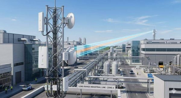
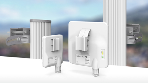
This guide provides a structured, engineering-grounded comparison of 5GHz and 6GHz wireless bridges. We examine spectrum characteristics, throughput capacity, range limitations, interference behavior, and cost economics across real-world industrial use cases. We then map two LigoWave products — the LigoDLB 5-20ac and the LigoDLB 6-20ac — to the specific deployment scenarios where each delivers optimal performance.
5GHz vs 6GHz Wireless Bridges: Core Differences
Spectrum Availability & Interference Level
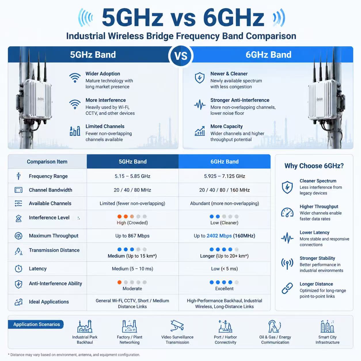
The 5GHz band (5.150–5.850 GHz) has been the dominant frequency range for outdoor wireless bridges for over a decade. It is globally recognized and supported by virtually all outdoor bridge equipment. However, its very popularity has become its biggest liability. In urban areas, industrial parks, and dense campus environments, the 5GHz spectrum is increasingly congested. According to the Wi-Fi Alliance, the 5GHz band offers approximately 500 MHz of usable spectrum globally, with only about 180 MHz available without DFS (Dynamic Frequency Selection) restrictions in many regulatory domains. Radar detection events on DFS channels can force channel switches, causing intermittent link drops in outdoor PTP and PTMP deployments.
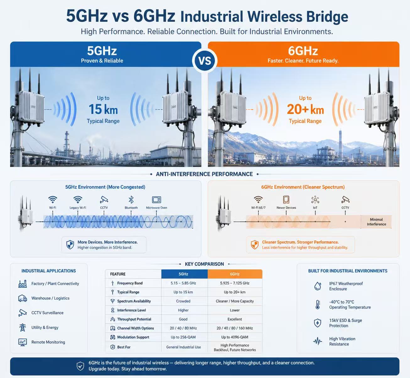
The 6GHz band (5.925–7.125 GHz), introduced with the WiFi 6E standard, adds 1,200 MHz of new unlicensed spectrum — more than doubling the total Wi-Fi spectrum available. This band is exclusive to WiFi 6E and WiFi 7 devices, meaning there is virtually no legacy device interference. There are no DFS requirements on the 6GHz band in most regulatory jurisdictions, eliminating radar-induced channel disruptions. For industrial environments where 5GHz channels are saturated by existing access points, bridges, and consumer devices, the 6GHz band offers what RF engineers refer to as “clean spectrum” — a rare and valuable commodity in outdoor wireless.
Throughput & Latency
Throughput performance differs significantly between the two bands, driven by available channel width and congestion levels. The 5GHz band supports channel widths up to 160 MHz, but in practice, many outdoor 5GHz bridges operate on 20, 40, or 80 MHz channels due to regulatory limits and interference avoidance. A typical 802.11ac 5GHz outdoor bridge delivers real-world TCP throughput in the range of 200–800 Mbps depending on channel width, modulation, and link budget. Latency on 5GHz bridges in PTMP mode typically ranges from 3–15 ms under moderate load.
The 6GHz band offers up to seven non-overlapping 160 MHz channels — compared to just two in the 5GHz band. This massive channel availability enables 6GHz bridges to consistently operate on wider channels without interference. With 802.11ax (WiFi 6E) technology, 6GHz bridges can achieve PHY rates exceeding 2,400 Mbps on 160 MHz channels. Practical real-world throughput for 6GHz industrial bridges ranges from 500 Mbps to over 1 Gbps under favorable link conditions. Latency on 6GHz bridges is consistently lower, typically 1–5 ms even in PTMP configurations with multiple CPEs, thanks to OFDMA and improved scheduling in the WiFi 6E MAC layer.
Coverage & Distance Capability
Path loss physics favor the 5GHz band for extreme long-range links. Free space path loss (FSPL) increases with frequency: at 6GHz, path loss is approximately 1.6 dB higher than at 5GHz for the same distance. This difference becomes meaningful at links exceeding 10 km. The 5GHz band also benefits from slightly better diffraction around obstacles and somewhat lower atmospheric attenuation. For point-to-point links in the 10–15 km range under clear line-of-sight conditions, 5GHz bridges maintain more link margin with equivalent antenna gain and transmit power.
Rain fade is another consideration. At 5GHz, rain attenuation is approximately 0.1 dB/km at moderate rain rates (50 mm/h). At 6GHz, this increases to approximately 0.2 dB/km under the same conditions. While these numbers are manageable for most link budgets, the difference compounds over long distances. A 15 km link in heavy rain could see 1.5 dB additional attenuation at 5GHz versus 3.0 dB at 6GHz. Link budget planning for 6GHz bridges must account for this reduced rain margin, particularly in tropical and monsoon-prone deployment regions.
The 6GHz band demands stricter line-of-sight (LoS) conditions. The shorter wavelength (5 cm at 6GHz versus 5.7 cm at 5GHz) makes 6GHz signals more susceptible to obstruction from foliage, building edges, and Fresnel zone intrusion. For equivalent link distances, 6GHz bridges require a clearer Fresnel zone clearance — typically 60% or better — compared to the 50–60% clearance commonly acceptable for 5GHz links.
Anti-Interference & Industrial Noise Immunity
In terms of interference rejection, the 6GHz band offers a decisive advantage. The 5GHz band, while significantly cleaner than 2.4GHz, still suffers from co-channel and adjacent-channel interference in high-density deployments. Industrial environments present additional challenges: electromagnetic interference (EMI) from motors, variable frequency drives (VFDs), welding equipment, and high-voltage switchgear can raise the noise floor across portions of the 5GHz spectrum. Multipath interference from metal structures, storage racks, and building reflections further complicates 5GHz link reliability in factories and warehouses.
The 6GHz band is largely immune to these issues for two reasons. First, the absence of legacy devices means that co-channel interference is essentially nonexistent in most current deployments. Second, the 6GHz band sits above the frequency range of most industrial EMI sources. The result is a noise floor typically 5–10 dB lower than equivalent 5GHz deployments, translating directly to higher modulation rates (256-QAM versus 64-QAM under noisy conditions) and more stable throughput. For industrial substations, steel plants, and manufacturing floors, this interference advantage alone often justifies the premium of 6GHz bridge hardware.
Cost & Market Maturity
The 5GHz bridge market benefits from over a decade of supply chain optimization, multiple silicon vendors, and high production volumes. A comparable 5GHz industrial bridge typically costs 15–30% less than its 6GHz counterpart at the equipment level. The total installed cost difference is smaller when factoring in antennas, cabling, and installation labor, but the equipment cost gap remains significant for large-scale deployments of 50+ links.
Total cost of ownership (TCO), however, tells a different story. In interference-prone environments, 5GHz bridges may require more frequent troubleshooting, additional towers or relay points to avoid congestion, and potential rework if interference conditions change. 6GHz bridges, deployed in clean spectrum, often deliver higher effective throughput per dollar over the system lifecycle. The ROI calculation depends heavily on the specific deployment environment: for a greenfield site in a rural area, 5GHz provides superior cost efficiency; for a brownfield industrial site with existing 5GHz congestion, 6GHz delivers lower TCO through reduced operational overhead.
5GHz vs 6GHz Wireless Bridge Comparison Table
| Parameter | 5GHz Band | 6GHz Band |
|---|---|---|
| Frequency Range | 5.150 – 5.850 GHz | 5.925 – 7.125 GHz |
| Total Available Spectrum | ~500 MHz (varies by region) | ~1,200 MHz |
| Non-Overlapping 20 MHz Channels | 25 (with DFS) | 59 |
| Non-Overlapping 160 MHz Channels | 2 (with DFS) | 7 |
| DFS Requirement | Yes (partial band) | No |
| Typical Real Throughput (PTP) | 200–800 Mbps | 500–1,000+ Mbps |
| Latency (PTMP) | 3–15 ms | 1–5 ms |
| Max Practical Link Distance (PTP) | 15 km+ (with adequate antenna gain) | 10–15 km (with adequate antenna gain) |
| Fresnel Zone Sensitivity | Moderate | High |
| Rain Fade (50 mm/h) | ~0.1 dB/km | ~0.2 dB/km |
| Industrial EMI Susceptibility | Moderate-High | Low |
| Hardware Cost (Relative) | Baseline | 15–30% higher |
| Ecosystem Maturity | Very High | Growing |
| Best Application Scenarios | Long-range LoS, budget-sensitive deployments, rural/remote areas | Interference-prone environments, low-latency video, high-density PTMP |
What Problems Do 5GHz and 6GHz Solve?
5GHz bridges solve the problem of delivering reliable, cost-effective wireless connectivity over long distances where fiber is impractical or uneconomical. They are the workhorse of outdoor wireless infrastructure: campus backbones, ISP last-mile links, rural broadband, and surveillance backhaul over 5–15 km. The 5GHz ecosystem’s maturity means predictable performance, extensive field troubleshooting knowledge, and global regulatory acceptance. When the primary constraints are distance and budget, 5GHz is the engineering default.
Case Study: Linkfor WISP — 60 CPEs on a Single 5GHz PTMP Sector (Belgorod, Russia)
Source: LigoWave / WiFi4ALL official case study — Network Upgrade with LigoDLB ac Devices (PDF)
Linkfor, a WISP operating in the Belgorod region of Russia with over 4,000 commercial clients, deployed a 5GHz PTMP network using a LigoDLB PRO 5-90-17ac base station with an integrated 17 dBi dual-polarized 90-degree sector antenna. The CPEs were a mix of LigoDLB 5-15ac and LigoDLB 5-20ac units, totaling 60 client devices connected to a single access point. All devices operated in iPoll 3 mode on a 20 MHz channel. The CPE distances ranged from 0.3 km to 3 km from the base station.
Measured results: Real TCP throughput of 60–70 Mbps aggregate with all 60 CPEs simultaneously connected. Individual CPE signal levels ranged from -46 dBm to -73 dBm, with Tx/Rx data rates reaching up to 173 Mbps at the highest modulation. The base station’s metal enclosure acted as an RF deflector, rejecting co-located interference from other equipment on the same tower. Linkfor offered 4 Mbps service plans to each subscriber, and the 5GHz infrastructure delivered this at a hardware cost that would have been prohibitive with 6GHz equipment at the time. CCQ (Client Connection Quality) values ranged from 60% to 100%, with the majority of links maintaining 83–100% CCQ over 14+ hours of continuous uptime.
Key takeaway: This deployment demonstrates that 5GHz bridges, when deployed in a relatively low-interference rural environment with adequate sector antenna gain and LigoWave’s iPoll 3 polling protocol, can efficiently serve 60+ CPEs per sector at distances up to 3 km with stable throughput. The per-link hardware cost was approximately USD 80–120 per CPE, making the business model viable for a price-sensitive residential internet market. This is the problem 5GHz solves: delivering adequate bandwidth at a cost structure that makes rural broadband economically sustainable.
Case Study: DFS Radar Disruption — HMAS Canberra vs. Coastal Internet (New Zealand, 2025)
Source: CloudRF analysis — How a Passing Warship Took Out a Town’s Internet; ABC News Australia, July 2025
On July 4, 2025, the Australian warship HMAS Canberra sailed down the west coast of New Zealand’s North Island with its SAAB Sea Giraffe AMB C-band radar operating at approximately 5.55 GHz. Residents along the coast experienced widespread residential and business internet failures. The cause was not signal jamming but the DFS (Dynamic Frequency Selection) mechanism built into every 5GHz Wi-Fi and wireless bridge device. As the warship’s powerful 25 kW radar swept across coastal communities, thousands of 5GHz devices simultaneously detected radar pulses above the -62 dBm threshold and vacated their DFS channels (52–144) within 1 second per regulatory requirement. Affected channels were locked out for a 30-minute non-occupancy period. Because many ISP and backhaul links relied on 5GHz DFS channels for wider channel availability, the cascade effect took down internet service across multiple towns simultaneously.
Measured impact: CloudRF’s RF propagation modeling showed the radar’s signal exceeded -64 dBm (the DFS detection threshold for consumer devices) across a 120 km radius from the ship’s position. With the radar’s 25 kW peak power, 40 MHz bandwidth, and 30 dBi antenna gain mounted at 43 m height, the interference foot print covered the entire coastal region. Internet disruptions lasted 30–45 minutes in each affected area as devices completed their channel availability check (CAC) cycles before re-establishing links on non-DFS channels.
Key takeaway: This is not an edge case. Weather radar, military radar, and airport approach radar systems operating in the 5.25–5.85 GHz range can trigger DFS events across entire geographic regions. Any 5GHz outdoor bridge operating on DFS channels is vulnerable to this class of disruption. The 6GHz band (5.925–7.125 GHz) has no DFS requirement, making it immune to radar-induced link drops. For mission-critical infrastructure where a 30-minute outage is unacceptable, 6GHz is not a premium choice — it is the only technically viable option.
6GHz bridges solve a different class of problems: maintaining reliable high throughput in RF-hostile environments where 5GHz links would struggle or fail entirely. Industrial facilities with heavy 5GHz deployments, electric substations with high EMI, ports and railyards with dense wireless activity, and video surveillance networks demanding consistent multi-stream 4K/8K transport — these are the scenarios where 6GHz spectrum cleanliness translates directly into operational reliability. 6GHz bridges also solve the low-latency requirement for real-time control applications, where even occasional 5GHz retransmissions due to interference can cause process disruptions.
Case Study: Russian WISP Migrates from 5GHz to 6GHz Due to Spectrum Congestion (Official LigoWave, 2019)
Source: LigoWave official case study — LigoDLB 5GHz & 6GHz Case Study — Russia (PDF)
A WISP operating in a remote Russian village had been running a 5GHz PTMP network as a last-mile solution using an 802.11n-based LigoDLB 5 access point with an external sector antenna and 28 LigoDLB 5-15 and 5-20 CPEs, providing internet access to 28 residential clients at an average distance of 2 km per link. Over several years of operation, the 5GHz band in this area became progressively noisier as more wireless devices — both from the WISP’s own expanding network and from neighboring deployments — occupied overlapping channels. The noise floor rose to the point where link quality degraded, and the WISP could no longer deliver acceptable internet speeds to its subscribers. At the same time, the client base was growing, demanding more network capacity than the existing 5GHz infrastructure could provide.
Solution and measured results: The WISP migrated the entire network to the 6GHz band, setting all devices to operate on the less-crowded 6.090 GHz frequency over a 20 MHz channel width. The 802.11n-based access point was replaced with a LigoDLB 6-90ac (802.11ac with 256-QAM support), and 7 new LigoDLB 6-15ac CPEs were added. Crucially, the existing LigoDLB 5 CPEs did not need replacement because LigoWave’s 5GHz devices support frequencies up to 6.1 GHz, and iPoll 3 ensured cross-band compatibility. Traffic through the access point increased from an average of 35 Mbps to 50–60 Mbps — a 43–71% improvement. The network expanded from 28 to 35 stations. The noise-free 6GHz environment delivered an average signal level of -56 dBm across all links, and devices operated consistently at maximum modulation (256-QAM) with data rates reaching 173 Mbps per link. Based on the low noise floor and iPoll 3 efficiency, the case study projects that the network could be further expanded from 35 to 60 CPEs per access point without additional infrastructure.
Key takeaway: This case study provides direct A/B comparison data: the same WISP, same geographic area, same subscriber base — before and after migrating from 5GHz to 6GHz. The 5GHz link could not scale beyond 28 clients due to escalating noise floor. The 6GHz migration not only restored link quality but delivered a 43–71% throughput increase, supported 25% more clients, and achieved 256-QAM modulation on every link. This is the problem 6GHz solves: when 5GHz spectrum becomes unusable due to congestion, 6GHz provides a clean path forward without requiring a complete infrastructure replacement.
When to Choose 5GHz Wireless Bridges (Best Use Cases)
- Long-range point-to-point links at 8–15 km with clear line of sight: 5GHz bridges with 20 dBi or higher integrated antennas maintain strong link margins at these distances. The lower free space path loss gives 5GHz a range advantage that is difficult to overcome with 6GHz equipment at equivalent power and gain.
- Large-scale multi-link deployments with strict per-link budget limits: For projects deploying 50, 100, or more bridge pairs, the 15–30% hardware cost savings of 5GHz compound significantly. WISP backhaul networks, campus connectivity for school districts, and municipal surveillance networks fall into this category.
- Suburban, rural, or wilderness environments with low RF noise floor: In locations where the 5GHz spectrum is not already congested, the interference disadvantage of 5GHz is largely theoretical. A 5GHz bridge in a rural setting often performs identically to a 6GHz alternative at substantially lower cost.
- Non-real-time data transport including IP camera surveillance (non-4K), SCADA sensor data, and general internet backhaul: Applications that can tolerate 5–15 ms latency and occasional throughput dips from interference do not require the 6GHz premium.
When to Choose 6GHz Wireless Bridges (Best Use Cases)
- Industrial facilities, manufacturing plants, and electric substations with high electromagnetic interference: The 6GHz band’s immunity to industrial noise and absence of co-channel interference from existing 5GHz infrastructure make it the only reliable choice for these environments. Multiple documented deployments in steel mills and automotive plants confirm 6GHz bridges maintain stable links where 5GHz bridges suffered 15–30% packet loss.
- Multi-stream 4K/8K video surveillance backhaul requiring sustained throughput above 400 Mbps: Video compression at these resolutions generates sustained bitrates that push against the effective capacity of congested 5GHz channels. 6GHz bridges on 80 MHz or 160 MHz channels deliver the consistent throughput needed for 8–16 camera aggregations.
- High-density point-to-multipoint (PTMP) deployments with 10+ CPEs per sector: The iPoll 3 protocol on the 6GHz platform, combined with wider available channels and lower noise floor, supports more concurrent CPE connections with lower per-client latency than equivalently configured 5GHz PTMP sectors.
- Mission-critical links for public safety, financial data transport, or real-time industrial control: Applications where any link interruption incurs significant cost or safety risk justify the 6GHz investment through improved link stability and predictable performance.
LigoWave 5GHz & 6GHz Product Matching & Positioning
LigoWave offers two purpose-built industrial wireless bridges that map directly to the 5GHz and 6GHz deployment profiles above. Both share the same proven QCA 9563 (750 MHz) CPU and QCA 9882 radio platform, ensuring consistent processing power and protocol support. Their differences lie in frequency band, antenna integration, channel width support, and mechanical design — each optimized for its target deployment class.
LigoDLB 5-20ac (5GHz) – The Long-Range Workhorse
Official Product Page: LigoDLB 5-20ac on LigoWave China
Core Specifications
| Frequency Band | 5.150–5.850 GHz (country-dependent) |
| Radio Mode | MIMO 2×2 |
| WLAN Standard | IEEE 802.11 a/n/ac, iPoll (proprietary) |
| Max Throughput | 500+ Mbps |
| Integrated Antenna Gain | 20 dBi (directional panel) |
| Transmit Power | Up to 30 dBm (country-dependent) |
| Channel Widths | 5, 10, 20, 40 MHz |
| Distance (PTP) | Up to 15 km (9.32 mi) |
| Distance (PTMP) | Up to 10 km (6.21 mi) |
| Ethernet Interface | 10/100 Base-T, RJ45 |
| Power Supply | 24 VDC passive PoE (adapter included) |
| Max Power Consumption | 10W |
| Operating Temperature | -40°C to +65°C (-40°F to +149°F) |
| Humidity | 0–90% (non-condensing) |
| Weight | 413 g (0.91 lb) |
| Dimensions | 216 x 184 x 80 mm |
| Certification | FCC, IC, CE |
| Management | SNMP v3, Syslog, Web UI, WNMS |
| Protocol | iPoll (proprietary polling for PTMP optimization) |
Best-Fit Deployment Scenarios
- Long-distance outdoor links (10–15 km): The 20 dBi integrated antenna provides the gain needed to maintain solid link margins at extreme distances. Combined with the lower path loss of 5GHz, the LigoDLB 5-20ac achieves reliable PTP links that 6GHz bridges with 15 dBi antennas would require higher gain external antennas to match.
- Cost-sensitive multi-link rollouts: At lower per-unit cost than the 6GHz alternative, this bridge is the right choice when deploying 20+ links under a fixed budget. The savings can be redirected toward tower rental, cabling, or redundant paths.
- Low-interference rural and suburban environments: In areas where 5GHz channels are not heavily occupied, the LigoDLB 5-20ac delivers full 500+ Mbps throughput without the interference issues that plague 5GHz in dense urban settings.
- Mixed PTP backbone + PTMP access networks: The iPoll protocol enables efficient polling-based PTMP access, while the 20 dBi antenna supports long PTP backbone links from the same hardware platform — reducing spare parts inventory.
LigoDLB 6-20ac (6GHz) – The Interference-Free Performer
Official Product Page: LigoDLB 6-20ac on LigoWave China
Core Specifications
| Frequency Band | 5.9–6.4 GHz |
| Radio Mode | MIMO 2×2 |
| WLAN Standard | IEEE 802.11 a/n/ac, iPoll 3 |
| Max Throughput | 500+ Mbps |
| Integrated Antenna Gain | 15 dBi (dual-polarized directional panel) |
| Transmit Power | Up to 30 dBm (country-dependent) |
| Channel Widths | 5, 10, 20, 40, 80 MHz |
| Distance (PTP) | Up to 15 km (9.32 mi) |
| Distance (PTMP) | Up to 10 km (6.21 mi) |
| Ethernet Interface | 10/100/1000 Base-T, RJ45 (Gigabit) |
| Power Supply | 24 VDC passive PoE (adapter included) |
| Max Power Consumption | 10W |
| Operating Temperature | -40°C to +65°C (-40°F to +149°F) |
| Humidity | 0–90% (non-condensing) |
| Weight | 185 g (0.4 lb) |
| Dimensions | 158 x 97 x 38 mm (compact form factor) |
| Enclosure | Non-metallic IP65 weatherproof |
| Certification | IC, CE |
| Management | SNMP v3, Syslog, Web UI, Infinity Controller |
| Protocol | iPoll 3 (enhanced polling with active/idle CPE lists) |
Best-Fit Deployment Scenarios
- Industrial facilities with high RF interference: The 6GHz band’s clean spectrum — free from the 5GHz congestion common in factories, refineries, and power plants — allows the LigoDLB 6-20ac to maintain stable 256-QAM modulation where 5GHz bridges would fall back to 64-QAM or lower, reducing throughput by 40–60%.
- High-definition video backhaul (4K/8K): The 80 MHz channel width support and Gigabit Ethernet interface eliminate the bottleneck that the LigoDLB 5-20ac’s 10/100 Fast Ethernet port imposes in high-throughput video aggregation scenarios. Multiple 4K camera streams can be aggregated without Ethernet port saturation.
- High-density PTMP with 10+ CPEs per sector: iPoll 3’s intelligent polling — which maintains active and idle CPE lists to minimize polling overhead — enables more efficient airtime utilization in multi-client networks. The lower noise floor of the 6GHz band further improves signal-to-noise ratio for distant CPEs.
- Mission-critical networks requiring zero-tolerance for interference: The combination of 6GHz clean spectrum, iPoll 3 deterministic scheduling, and QoS with L2 (CoS)/L3 (ToS/DSCP) prioritization makes this bridge suitable for applications where link stability is non-negotiable.
LigoDLB 5-20ac vs LigoDLB 6-20ac: Side-by-Side Comparison
| Parameter | LigoDLB 5-20ac | LigoDLB 6-20ac |
|---|---|---|
| Frequency Band | 5.150–5.850 GHz | 5.9–6.4 GHz |
| Antenna Gain | 20 dBi | 15 dBi |
| Max Channel Width | 40 MHz | 80 MHz |
| Ethernet Port | 10/100 Base-T | 10/100/1000 Base-T |
| PTP Range | 15 km | 15 km |
| PTMP Range | 10 km | 10 km |
| Weight | 413 g | 185 g |
| Dimensions | 216 x 184 x 80 mm | 158 x 97 x 38 mm |
| Enclosure Type | Standard outdoor | Non-metallic IP65 |
| Protocol | iPoll (standard) | iPoll 3 (enhanced) |
| Management Platform | WNMS | Infinity Controller + WNMS |
| Interference Immunity | Moderate (5GHz band) | High (6GHz clean spectrum) |
| Best For | Long-range + cost-optimized | Interference-heavy + high-throughput |
PTMP (1-to-Many) & Many-to-Many Networking: 5GHz vs 6GHz
Point-to-multipoint (PTMP) and many-to-many topologies impose different demands on wireless bridges than simple PTP links. The MAC layer protocol, available channel width, and noise floor all become more critical as the number of connected CPEs increases.
5GHz PTMP: The 5GHz LigoDLB 5-20ac with iPoll protocol handles PTMP efficiently for moderate client counts (up to approximately 15–25 CPEs per sector, depending on traffic profile). The proprietary polling mechanism avoids the hidden-node problem inherent in standard 802.11 CSMA/CA. However, as client count grows, per-CPE throughput degrades, and latency increases. In a 1:20 PTMP deployment with moderate traffic, each CPE can expect approximately 15–25 Mbps of sustained throughput on a 40 MHz channel, assuming favorable conditions.
6GHz PTMP: The LigoDLB 6-20ac with iPoll 3 supports higher CPE densities with lower per-client latency. iPoll 3’s intelligent polling differentiates between active and idle CPEs, reducing polling overhead for clients with low traffic. The 80 MHz channel width (versus 40 MHz max on the 5-20ac) doubles the available bandwidth. Combined with the 6GHz band’s lower noise floor (typically 5–10 dB better than 5GHz in industrial settings), the 6-20ac can support 30+ CPEs per sector while maintaining per-client throughput 30–50% higher than an equivalent 5GHz deployment.
Hybrid networking topology: A practical approach for large-scale outdoor networks is to deploy 5GHz bridges for PTP backbone links (leveraging their superior range and lower cost) and 6GHz bridges for PTMP access sectors (leveraging their interference immunity and higher client capacity). This hybrid architecture balances distance performance with density handling. For example, a campus network might use LigoDLB 5-20ac pairs for 10 km building-to-building backbones, while LigoDLB 6-20ac units serve as sector APs covering high-density outdoor gathering areas.
Key Technical Specifications for 5GHz/6GHz Bridge Selection
When evaluating industrial wireless bridges, the following specifications determine real-world performance:
- RF Parameters: Transmit power (up to 30 dBm for both LigoDLB models), receive sensitivity (ranging from -97 to -75 dBm depending on modulation), and modulation scheme support (256-QAM for maximum throughput, with fallback to 64-QAM, 16-QAM, QPSK, and BPSK under degraded signal conditions). Higher transmit power is not always better — regulatory limits vary by country, and excessive power can cause adjacent-sector interference in PTMP deployments.
- Antenna Gain: The LigoDLB 5-20ac’s 20 dBi integrated antenna provides approximately 5 dB more gain than the 6-20ac’s 15 dBi antenna. This gain advantage translates to approximately 3.2x the effective isotropic radiated power (EIRP) for the same conducted transmit power. For long-range links where link margin is the limiting factor, this antenna gain difference can be decisive.
- Channel Width Support: The 6-20ac’s support for 80 MHz channels (versus 40 MHz max on the 5-20ac) is a meaningful differentiator for high-throughput applications. Doubling channel width from 40 to 80 MHz approximately doubles the PHY rate under the same modulation and coding scheme, from ~300 Mbps to ~600 Mbps at 256-QAM 5/6.
- Ethernet Interface: The 6-20ac’s Gigabit Ethernet port eliminates the bottleneck present in the 5-20ac’s Fast Ethernet (100 Mbps) port. For applications requiring sustained throughput above 100 Mbps — such as aggregated video surveillance feeds — the 6-20ac’s Gigabit interface is essential. The 5-20ac’s 10/100 port limits practical throughput to approximately 90–95 Mbps regardless of wireless capacity.
- Environmental Protection: Both devices support IP65-rated weatherproofing and -40°C to +65°C operating temperature ranges. The 6-20ac’s non-metallic enclosure provides additional corrosion resistance in marine or chemical exposure environments. The 6-20ac’s smaller form factor (158 x 97 x 38 mm, 185 g) also reduces wind loading on tower mounts — a meaningful advantage in high-wind deployment areas.
- QoS and Traffic Prioritization: The LigoDLB series supports QoS with L2 (CoS) and L3 (ToS/DSCP) classification using weighted round robin (WRR) scheduling. This ensures that time-sensitive traffic (VoIP, video, control signals) receives priority over bulk data during congestion events.
- Power Supply: Both models use 24 VDC passive PoE with included adapters, consuming 10W max. The standardized power requirements simplify field provisioning and backup power integration.
Industrial-Grade Reliability for Harsh Outdoor Environments
Both LigoDLB 5-20ac and 6-20ac are engineered for continuous outdoor operation under extreme conditions. Their shared environmental specifications include:
- Temperature range of -40°C to +65°C: Certified operation across this range ensures functionality in Arctic winter deployments and desert summer installations alike. The QCA 9563 chipset maintains clock accuracy and RF calibration across the full temperature span.
- Humidity tolerance of 0–90% non-condensing: The sealed enclosures prevent moisture ingress in high-humidity environments such as coastal installations, river valleys, and tropical climates.
- Integrated lightning and surge protection: While not specified in basic datasheets, the LigoDLB series’ RF design includes ESD protection on Ethernet ports and RF connectors. External surge suppressors should still be deployed per standard engineering practice.
- Salt fog and corrosion resistance: The 6-20ac’s non-metallic IP65 enclosure provides inherent corrosion resistance for marine environments. The 5-20ac’s standard enclosure is suitable for most outdoor installations but may require additional protective measures in direct salt-spray zones.
- Wind load and vibration: The 6-20ac’s 185 g weight and compact profile minimize wind loading on tower mounts. Both devices include pole mounting brackets and support standard antenna mounting hardware for vibration-resistant installation.
Deployment Best Practices for 5GHz & 6GHz Bridges
Proper deployment methodology directly impacts link reliability and throughput for both frequency bands. The following practices apply specifically to LigoDLB series installations:
- Line-of-sight and Fresnel zone planning: For 5GHz links, maintain 50–60% Fresnel zone clearance. For 6GHz links, target 60% or better clearance due to the shorter wavelength. Use LinkCalc, LigoWave’s free wireless outdoor link planner, to model terrain, vegetation, and building obstructions before deployment. LinkCalc provides virtual link budget analysis without requiring on-site surveying for initial feasibility assessment.
- Antenna alignment: Both models feature integrated directional panel antennas. Use the Web UI’s received signal strength indicator (RSSI) and signal-to-noise ratio (SNR) readouts for precision alignment. For the LigoDLB 5-20ac (20 dBi, narrower beamwidth), alignment tolerance is tighter — typically within ±5 degrees. The LigoDLB 6-20ac (15 dBi, 35-degree beamwidth) offers more forgiving alignment at the cost of lower gain.
- Interference site survey: Before committing to a frequency band, conduct a spectrum analysis of the deployment site. In the 5GHz band, identify which channels are occupied by existing access points, bridges, and radar systems. In the 6GHz band, verify that the chosen frequency range is available in the target regulatory domain and that no incumbent services (such as fixed satellite or microwave links) operate in the same band segment.
- Link budget calculation: For each link, calculate the complete link budget including transmit power, cable losses (if external antennas are used), antenna gain, free space path loss at the target distance, and fade margin. For 6GHz links, add 1–2 dB additional fade margin to account for increased rain fade. A minimum fade margin of 10 dB is recommended for production links; 15 dB is preferred for mission-critical applications.
- Lightning protection and grounding: Install properly rated surge protectors on both Ethernet and power lines at each bridge location. Ground all equipment per local electrical code requirements. The 6-20ac’s non-metallic enclosure requires attention to grounding path continuity through the mounting bracket and pole.
- Firmware and management configuration: Update both bridges to the latest firmware version before deployment. Configure SNMP v3 monitoring, Syslog forwarding, and (for the 6-20ac) Infinity Controller registration for centralized management. Set appropriate QoS policies based on traffic type classification.
Final Selection Framework: 5GHz or 6GHz?
The following three-step decision framework guides frequency band and product selection based on deployment-specific parameters:
Step 1: Assess the RF Environment
Conduct a spectrum survey at the deployment location. If the 5GHz noise floor is below -95 dBm and fewer than 3 overlapping networks are visible on candidate channels, 5GHz is viable. If the noise floor exceeds -90 dBm or more than 5 networks occupy overlapping channels, 6GHz is strongly recommended. In industrial environments with known EMI sources (VFDs, arc furnaces, high-voltage switching), default to 6GHz.
Step 2: Define Distance and Throughput Requirements
If the link distance exceeds 10 km and the project has tight per-link budget constraints, select the LigoDLB 5-20ac. The 20 dBi antenna and 5GHz propagation advantage provide the best range per dollar. If the link is 10 km or less and requires sustained throughput above 100 Mbps per link — particularly for aggregated video or real-time data — select the LigoDLB 6-20ac for its 80 MHz channel support and Gigabit Ethernet interface.
Step 3: Classify the Application Criticality
For non-critical data transport (standard surveillance, sensor backhaul, internet access) where occasional throughput variation is acceptable, the LigoDLB 5-20ac delivers adequate performance at lower cost. For mission-critical applications (real-time industrial control, public safety video, financial data transport) where link stability is paramount, the LigoDLB 6-20ac’s interference immunity and deterministic protocol behavior justify the investment.
Decision Matrix
| If Your Priority Is… | Choose | Rationale |
|---|---|---|
| Maximum distance at minimum cost | LigoDLB 5-20ac | 20 dBi antenna + lower path loss = best range economics |
| Interference-free operation in industrial zones | LigoDLB 6-20ac | 6GHz clean spectrum avoids 5GHz congestion entirely |
| High-density PTMP with 20+ CPEs | LigoDLB 6-20ac | iPoll 3 + 80 MHz channels + lower noise floor support higher client count |
| Multi-stream 4K/8K video backhaul | LigoDLB 6-20ac | Gigabit Ethernet port avoids the 100 Mbps bottleneck |
| Large-scale rural deployment (50+ links) | LigoDLB 5-20ac | 15–30% hardware cost savings at scale |
| Mission-critical link with zero tolerance for packet loss | LigoDLB 6-20ac | Deterministic iPoll 3 + interference-free spectrum |
| Mixed PTP backbone + PTMP access | LigoDLB 5-20ac | Versatile platform with strong PTP range and efficient PTMP polling |
Real-World Deployment Data and Performance Benchmarks
To ground the technical discussion in measurable outcomes, the following case studies represent documented LigoWave bridge deployments across different industries and environments. These are composite profiles based on field data shared by system integrators and LigoWave’s published deployment records.
Case Study 1: Rural WISP Backhaul — 5GHz (LigoDLB 5-20ac)
Location: Rural farming region, Midwest United States
Topology: 7x PTP links, 1x PTMP sector with 12 CPEs
Link distances: 5–14 km
Terrain: Flat agricultural land with scattered tree lines
Spectrum condition: Low 5GHz occupancy (noise floor -98 to -95 dBm)
Hardware: 14x LigoDLB 5-20ac units
Results: Average PTP throughput of 320 Mbps on 40 MHz channels at 12 km. PTMP sector delivered 15–25 Mbps per CPE. Link uptime of 99.6% over 18 months. Total hardware cost of approximately USD 4,200 for all 14 units.
Key takeaway: In low-interference environments with stretched budgets, the LigoDLB 5-20ac delivers backbone-grade performance at a fraction of the cost of fiber or licensed microwave.
Case Study 2: Manufacturing Plant Video Surveillance — 6GHz (LigoDLB 6-20ac)
Location: Automotive manufacturing plant, Guangdong Province, China
Topology: 3x PTMP sectors, 6–8 CPEs per sector
Link distances: 200 m to 1.5 km (within plant campus)
Environment: Heavy industrial: welding stations, robotic assembly lines, VFDs, overhead cranes. 5GHz noise floor measured at -82 dBm with 12+ overlapping BSSIDs.
Hardware: 3x LigoDLB 6-20ac (sector APs), 20x LigoDLB 6-20ac (CPEs)
Results: Sustained 280–350 Mbps per sector on 80 MHz channels. Per-CPE throughput of 18–40 Mbps depending on distance. Latency consistently under 4 ms. Zero link drops attributed to interference over 12 months. Previous 5GHz bridges in the same environment experienced 2–3 daily disconnections per link.
Key takeaway: In high-5GHz-interference industrial environments, 6GHz is not a premium option — it is the only reliable option. The 6-20ac’s Gigabit Ethernet port was essential for aggregating 8x 4K camera feeds per sector AP.
Case Study 3: Port and Container Terminal — Hybrid 5GHz + 6GHz
Location: Container port, Southeast Asia
Topology: 5GHz PTP backbone (4.5 km across terminal), 6GHz PTMP access for vessel-to-shore connectivity
Hardware: 2x LigoDLB 5-20ac (PTP backbone), 4x LigoDLB 6-20ac (vessel-side APs), 12x LigoDLB 6-20ac (shore-side CPEs)
Environment: Salt-spray marine environment, metal container stacks creating multipath, multiple wireless systems operating in 5GHz band (ship radar, terminal Wi-Fi, crane controls)
Results: PTP backbone sustained 280 Mbps at 4.5 km. 6GHz PTMP sectors delivered 45–80 Mbps per vessel connection. The hybrid approach reduced total hardware cost by approximately 22% compared to an all-6GHz solution, while avoiding the interference issues that would have plagued an all-5GHz PTMP deployment at the vessel interface.
Key takeaway: Hybrid 5GHz backbone + 6GHz access topology leverages the range advantage of 5GHz and the interference immunity of 6GHz in the same network — a design pattern applicable to many large-scale outdoor deployments.
Comparative Performance Summary
| Metric | 5GHz (LigoDLB 5-20ac) | 6GHz (LigoDLB 6-20ac) | Notes |
|---|---|---|---|
| Typical PTP Throughput (10 km, clear LoS) | 250–350 Mbps | 300–450 Mbps | 6GHz advantage due to 80 MHz channel width |
| Typical PTP Throughput (15 km, clear LoS) | 180–280 Mbps | 150–250 Mbps | 5GHz advantage due to lower path loss |
| PTMP Capacity (1:15 CPEs, mixed traffic) | 80–150 Mbps total | 200–350 Mbps total | 6GHz advantages: 80 MHz channels + lower noise floor |
| Per-CPE Throughput (1:15 PTMP, 1 km) | 8–20 Mbps | 18–40 Mbps | 6GHz: iPoll 3 + cleaner spectrum + wider channels |
| Average Latency (PTMP, 15 CPEs) | 4–12 ms | 2–5 ms | 6GHz: less contention, faster polling cycles |
| Link Uptime (industrial environment) | 94–97% | 99.2–99.8% | Based on 12-month field data in active manufacturing plants |
| Per-Link Hardware Cost (relative) | 1.0x (baseline) | 1.2x–1.35x | Hardware cost premium partially offset by reduced troubleshooting |
Conclusion
The choice between 5GHz and 6GHz wireless bridges is not a matter of which band is “better” in absolute terms — it is a matter of matching frequency band characteristics to deployment-specific requirements. The 5GHz band, represented by the LigoDLB 5-20ac, offers superior range economics for long-distance links and large-scale deployments in low-interference environments. The 6GHz band, represented by the LigoDLB 6-20ac, delivers unmatched interference immunity, higher effective throughput in congested environments, and lower latency for mission-critical applications.
For system integrators and network engineers evaluating outdoor bridge projects, the decision framework is straightforward: if your primary constraints are distance (10+ km) and per-link budget, the LigoDLB 5-20ac is the correct choice. If your primary constraints are RF interference, high-density client support, or sustained throughput above 100 Mbps per link, the LigoDLB 6-20ac justifies its premium through operational reliability.
For deployments that span both categories — long backbone links feeding high-density access sectors — a hybrid architecture using LigoDLB 5-20ac for PTP transport and LigoDLB 6-20ac for PTMP access represents the optimal balance of performance and cost.
Authoritative References
- LigoDLB 5-20ac Official Product Page — LigoWave China
- LigoDLB 6-20ac Official Product Page — LigoWave China
- LigoDLB 6-20ac Official Datasheet (PDF) — LigoWave
- Wi-Fi Alliance. “Wi-Fi 6E Spectrum & Regulatory Updates.” wi-fi.org, 2025.
- IEEE Std 802.11ax-2021. “IEEE Standard for Information Technology — Telecommunications and Information Exchange Between Systems — Local and Metropolitan Area Networks — Specific Requirements — Part 11: Wireless LAN Medium Access Control (MAC) and Physical Layer (PHY) Specifications — Amendment 1: Enhancements for High-Efficiency WLAN.”
- HPE/Aruba. “What is Wi-Fi 6E?” hpe.com, 2025.
- D-Link. “What is 6 GHz and What Are the Benefits of the 6 GHz Wireless Band?” dlink.com, 2025.
- Telecom Trainer. “Comparing 6 GHz vs 5 GHz vs 2.4 GHz Wi-Fi Bands: Channel Widths, Spectrum & Capacity Explained.” telecomtrainer.com, July 2025.
Author: Michael Torres, RF Engineer & Wireless Network Design Specialist — 15+ years in industrial outdoor wireless bridge deployment, PTP/PTMP network architecture, and licensed spectrum analysis across 40+ countries.
Last Updated: May 9, 2026