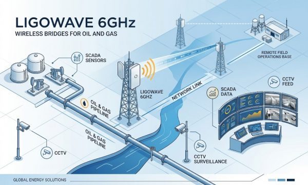
Deploying LigoWave 6GHz Wireless Bridges for Oil and Gas Pipeline SCADA and Video Surveillance
Deploying LigoWave 6GHz Wireless Bridges for Oil and Gas Pipeline SCADA and Video Surveillance
← Back to Complete Guide to LigoWave 6GHz Wireless Bridges
Key Overview
Who This Article is For: Oil and gas pipeline operators, SCADA system integrators, industrial automation engineers, and infrastructure project managers evaluating wireless backhaul solutions for pipeline monitoring, leak detection, security surveillance, and remote valve control applications along linear pipeline routes.
The Core Challenge: Oil and gas pipelines can extend hundreds or thousands of kilometers through remote terrain with no existing communications infrastructure. Traditional fiber optic deployment is cost-prohibitive at $20,000-50,000 per kilometer, while satellite links suffer from high latency (600ms+) and recurring bandwidth costs. LigoWave’s 6GHz wireless bridge products, particularly the LigoPTP RapidFire series with its daisy-chain topology support, dual Gigabit Ethernet ports, and PoE passthrough capability, provide a carrier-grade wireless alternative purpose-built for linear infrastructure monitoring.
Key Conclusion: A daisy-chain topology using LigoPTP RapidFire 6-N devices (700Mbps per link, W-Jet 5 protocol, IP-67, IEC Class 4 surge protection) spaced at 10-30km intervals along a pipeline route provides a cost-effective, high-capacity communications backbone. LigoDLB 6-20ac devices serve as local aggregation points for video cameras and sensors at each monitoring station (500Mbps+, 20dBi integrated antenna). For shorter pipeline segments under 7km per hop, LigoDLB 6-15ac devices offer a lower-cost alternative with 10W power consumption suitable for solar-powered remote stations. The LigoDLB 5ac provides 5GHz flexibility for sites requiring external antenna configurations. All specifications referenced from ligowave-cn.com.
Communications Challenges in Pipeline Monitoring
Pipeline Monitoring Data Requirements
A modern oil or gas pipeline monitoring system generates data from multiple sources at each monitoring station along the pipeline route. A typical monitoring station requires the following data streams:
- SCADA telemetry: 1-5 Mbps per station for pressure, temperature, flow rate, valve status, and cathodic protection monitoring data. This traffic is latency-sensitive (sub-50ms preferred) but low-bandwidth.
- Video surveillance: 15-50 Mbps per station for 3-5 HD cameras monitoring valve stations, pumping stations, and pipeline rights-of-way. Video traffic is bandwidth-intensive and benefits from consistent throughput.
- Leak detection sensors: 0.5-2 Mbps per station for acoustic sensors, fiber optic interrogation units, and gas detection systems. This data is critical for safety and requires reliable delivery.
- Remote shutdown/valve control: Minimal bandwidth but requires extremely low latency (under 100ms round-trip) and deterministic delivery guarantees.
When aggregated across a pipeline with monitoring stations every 10-30km, the total bandwidth requirement per link segment ranges from 20-200 Mbps depending on the density of monitoring equipment. LigoWave’s 6GHz products, with throughput ranging from 500Mbps (LigoDLB series) to 700Mbps (LigoPTP RapidFire series), provide sufficient headroom for current requirements and future expansion.
Why Traditional Communications Approaches Fall Short
Pipeline operators evaluating communications infrastructure face significant trade-offs with traditional approaches:
- Fiber optic deployment provides unlimited bandwidth and immunity to interference, but trenching or aerial installation along a pipeline route costs $20,000-50,000 per kilometer. For a 500km pipeline, fiber deployment alone can cost $10-25 million.
- Satellite communications offers global coverage but introduces 600ms+ latency, which is incompatible with real-time valve control and makes high-definition video surveillance impractical. Monthly bandwidth costs for 50Mbps satellite links typically exceed $2,000-5,000 per site.
- Cellular networks (4G/5G) provide adequate bandwidth in urban areas but coverage along pipeline routes is typically limited or non-existent in remote regions where pipelines are commonly located.
Wireless bridge technology, particularly in the 6GHz band, fills this gap by providing fiber-like throughput at a fraction of the deployment cost, with the additional advantages of rapid deployment, flexibility to accommodate route changes, and equipment reusability.
LigoWave Network Architecture for Linear Pipeline Routes
Architecture Overview: Daisy-Chain Backbone + Local Aggregation
The recommended network architecture for pipeline monitoring consists of two tiers:
Tier 1 Backhaul Backbone: LigoPTP RapidFire 6-N devices deployed at monitoring stations along the pipeline route, spaced at 10-30km intervals depending on terrain and antenna configuration. Each 6-N connects via a high-gain external antenna (25-30dBi parabolic dish) to the next 6-N in the chain, forming a linear wireless backbone. The dual Gigabit Ethernet ports on each 6-N allow passthrough of data from upstream devices, with one port carrying the aggregated traffic from the entire chain toward the central control center and the other port handling local station data. The PoE passthrough feature on the second Ethernet port can power downstream equipment or additional wireless devices at each station.
Tier 2 Local Aggregation: LigoDLB 6-20ac or LigoDLB 6-15ac devices deployed at each monitoring station to aggregate local video cameras, SCADA sensors, and IoT devices. The integrated antennas (20dBi or 15dBi) provide sufficient gain for local connectivity within the station area (typically 100-500m radius). The LigoDLB devices connect to the LigoPTP 6-N through the local Ethernet switch at each station. The 10W power consumption of the LigoDLB series makes these devices suitable for solar-powered stations where power availability is limited.
Redundancy and Ring Topology Options
For pipelines requiring high availability, a ring topology can be implemented by closing the daisy-chain loop connecting the final device in the chain back to the control center through an alternative path. LigoPTP RapidFire 6-N devices with dual Ethernet ports support this configuration through standard Ethernet ring protocols (RSTP/ERPS). In a ring configuration, a single link failure causes traffic to reroute through the alternative path, with restoration times typically under 50ms when using RSTP or under 20ms when using ERPS. The W-Jet 5 protocol maintains link stability during rerouting events, ensuring that SCADA traffic continues uninterrupted.
Network Capacity Planning
In a daisy-chain topology, each link segment carries the aggregated traffic of all downstream stations plus its own local traffic. For a pipeline with 20 monitoring stations and an average requirement of 50Mbps per station:
- The final link (nearest the control center) carries approximately 1,000Mbps of aggregated traffic.
- The LigoPTP RapidFire’s 700Mbps per link capacity means that the chain length is limited by bandwidth aggregation.
- A practical design limit is 10-12 stations per chain when each station consumes 50Mbps, or more stations when average per-station consumption is lower.
- For longer pipelines, the chain should be segmented, with multiple backbone chains connecting to the control center through fiber aggregation points at 100-150km intervals.
Product Selection for Pipeline Monitoring Segments
Backbone Link Selection: LigoPTP RapidFire 6-N
For the linear backbone connecting monitoring stations along a pipeline route, the LigoPTP 6-N RapidFire is the recommended device for several reasons specific to linear infrastructure deployments. The N-type connectors support high-gain parabolic antennas (typically 25-30dBi) required for the 10-30km link distances between monitoring stations. The 700Mbps throughput capacity provides sufficient headroom for aggregated video and SCADA traffic from multiple downstream stations. The dual Gigabit Ethernet ports with PoE passthrough enable the daisy-chain topology that is essential for linear routes. The IP-67 rating and IEC Class 4 surge protection provide reliability in the harsh environmental conditions typical of pipeline corridors, which are often exposed to extreme weather, dust, and electrical interference from pipeline cathodic protection systems.
The integrated 2.4GHz management radio is particularly valuable for pipeline deployments technicians can align antennas and verify link quality from ground level or during tower climbs without requiring a wired connection to the device. This reduces installation time at each station and minimizes the need for specialized alignment tools.
Local Aggregation: LigoDLB 6-20ac and LigoDLB 6-15ac
At each monitoring station, LigoDLB 6-20ac devices serve as the local aggregation point for video cameras and SCADA sensors. The 20dBi integrated antenna provides a 500Mbps+ wireless link that can aggregate up to 10 HD video cameras simultaneously, with the iPoll 3 protocol efficiently handling the constant-bitrate video traffic. The 6-20ac’s IP-65 rating is sufficient for the equipment shelter or pole-mounted installation at each station.
For solar-powered monitoring stations where power consumption is critical, the LigoDLB 6-15ac offers the same 500Mbps+ throughput with 10W power consumption, approximately 44% less than the LigoPTP RapidFire series’ 18W. The 6-15ac’s lighter weight (185g) and smaller form factor (158mm x 97mm x 38mm) also simplify mounting at locations with limited structural capacity.
Specialized Configurations: LigoDLB 5ac
The LigoDLB 5ac with its N-type connector external antenna support is recommended for pipeline monitoring locations where specific antenna configurations are required such as connecting stations located in deep valleys where a high-gain directional antenna is needed to achieve line-of-sight over intervening terrain, or where backward compatibility with existing 5GHz LigoWave infrastructure is required. The 5ac’s 20km maximum PTP distance (antenna dependent) makes it suitable for the longest pipeline segments where monitoring station spacing exceeds the 7km recommended maximum of the LigoDLB 6GHz models.
Product-to-Pipeline Segment Mapping
| Pipeline Segment | Distance | Bandwidth Required | Recommended Model | Key Specification |
|---|---|---|---|---|
| Main backbone trunk | 10-30 km per hop | 700 Mbps | LigoPTP 6-N RapidFire | N-connector for external ant., 30dBm, IP-67, 2x Gb PoE |
| Medium backbone trunk | 5-20 km per hop | 700 Mbps | LigoPTP 6-25 RapidFire | Integrated 25dBi, simpler install, same 700Mbps |
| Local station aggregation | Within 500m | 500 Mbps | LigoDLB 6-20ac | Integrated 20dBi, IP-65, 10W, 500Mbps+ |
| Solar-powered station | Within 500m | 500 Mbps | LigoDLB 6-15ac | 10W power, 185g, integrated 15dBi |
| Special antenna config. | Up to 20 km | 500 Mbps | LigoDLB 5ac | N-connector, 5.150-5.850GHz, external ant. |
Deployment Considerations for Remote Pipeline Environments
Lightning and Surge Protection
Pipeline monitoring stations are particularly vulnerable to electrical surges from two sources: lightning strikes (common in open terrain where pipelines are typically routed) and cathodic protection systems (which deliberately inject DC current into the pipeline for corrosion prevention, generating electrical noise that can couple into nearby Ethernet cables). The LigoPTP RapidFire series’ IEC Class 4 surge protection provides the highest level of integrated protection in LigoWave’s product line, making the 6-N and 6-25 the preferred choices for backbone links in lightning-prone areas. For LigoDLB series devices (6-15ac, 6-20ac, 5ac), the 3kV line-to-ground and 1kV line-to-line protection should be supplemented with external Ethernet surge protectors at both ends of the cable run, particularly where cables run parallel to the pipeline or enter equipment shelters.
Solar Power System Sizing
For remote pipeline monitoring stations without grid power, properly sizing the solar power system is critical. Based on LigoWave device power consumption:
- LigoDLB 6-15ac or 6-20ac (10W): A 50W solar panel with 40Ah battery provides 24/7 operation with approximately 4 hours of daily peak sunlight, assuming 5W average consumption (accounting for idle/low-traffic periods).
- LigoPTP 6-N or 6-25 (18W): A 100W solar panel with 80Ah battery is recommended for 24/7 operation under similar conditions.
- Mixed station (LigoPTP 6-N + LigoDLB 6-20ac + cameras): A 200W solar array with 150Ah battery bank is typically required, with the exact sizing dependent on camera count, heater/ventilation requirements, and local solar insolation data.
The LigoDLB series’ 10W power consumption provides a significant advantage for fully solar-powered stations, reducing solar panel and battery costs by approximately 50% compared to stations using LigoPTP RapidFire devices for local aggregation.
Antenna Tower and Mounting Considerations
Pipeline monitoring stations along linear routes typically use 10-30m towers or existing infrastructure (pipeline marker posts, valve station structures) for antenna mounting. For LigoPTP RapidFire 6-N devices with external antennas, the antenna should be mounted at sufficient height to achieve Fresnel zone clearance over intervening terrain. In flat terrain typical of pipeline routes, a 15m tower provides approximately 10-15km of line-of-sight range when combined with a 25dBi parabolic antenna. For the LigoDLB series devices with integrated antennas, pole-mounting at 5-10m height is typically sufficient for local station coverage within a 500m radius.
Bandwidth Planning for SCADA, Video, and Sensor Data
Traffic Classification and QoS Configuration
LigoWave OS supports IEEE 802.1p QoS prioritization, which should be configured to ensure that SCADA and valve control traffic receives priority over video and best-effort data. The recommended QoS classification for pipeline monitoring traffic is:
- Priority 7 (Network Control): LigoWave management traffic and network control protocols (STP, LLDP, etc.)
- Priority 5 (Critical): SCADA telemetry, valve control commands, leak detection alarms strict priority queuing with bandwidth guarantee
- Priority 3 (Video): Surveillance video streams rate-limited to prevent video from consuming excessive bandwidth during congestion events
- Priority 1 (Background): Log data, firmware updates, non-critical sensor telemetry best-effort delivery
When properly configured, the W-Jet 5 protocol on LigoPTP RapidFire links maintains sub-5ms latency for high-priority traffic even when the link is carrying near-capacity video and data traffic. This deterministic performance is essential for pipeline emergency shutdown systems that must respond to leak detection or pressure anomalies within milliseconds.
Per-Station Bandwidth Budget
| Monitoring Equipment | Bandwidth Per Unit | Units Per Station | Total Per Station |
|---|---|---|---|
| HD surveillance camera (1080p H.265) | 4-8 Mbps | 3-5 cameras | 12-40 Mbps |
| SCADA RTU (pipeline sensors) | 0.5-2 Mbps | 1-2 RTUs | 0.5-4 Mbps |
| Acoustic leak detector | 1-5 Mbps | 1-2 detectors | 1-10 Mbps |
| Cathodic protection monitor | 0.1-0.5 Mbps | 1 monitor | 0.1-0.5 Mbps |
| Environmental sensors | 0.05-0.1 Mbps | 5-10 sensors | 0.25-1 Mbps |
| Total per station | 14-55 Mbps |
With an average per-station requirement of 30Mbps, a LigoPTP RapidFire 6-N backbone link supporting 700Mbps can aggregate traffic from approximately 20 monitoring stations before reaching capacity. For pipelines requiring more stations per aggregation point, the network should be segmented with multiple backbone chains feeding into fiber aggregation points at the nearest accessible fiber optic termination.
Frequently Asked Questions
Q: Can LigoPTP RapidFire 6-N devices form a daisy-chain for linear pipeline monitoring?
Yes. The LigoPTP RapidFire 6-N features two Gigabit Ethernet ports (one with PoE passthrough), enabling daisy-chain topology. Each device connects to the next via its wireless link while the Ethernet ports carry aggregated traffic from downstream devices. The PoE passthrough port can power downstream equipment or additional wireless devices at intermediate stations. This design eliminates the need for external Ethernet switches at each monitoring station for the backbone path, reducing deployment cost and complexity. For specific configuration instructions for daisy-chain mode using the dual Ethernet ports, refer to the LigoPTP RapidFire user guide available at ligowave-cn.com/6g-50km-wireless-bridge.
Q: What is the recommended distance between pipeline monitoring stations using LigoWave devices?
The recommended station spacing depends on the device model and antenna configuration. For the LigoPTP 6-N with high-gain parabolic antennas (25-30dBi), spacing of 15-30km is achievable in flat terrain with clear line-of-sight. For the LigoPTP 6-25 with its integrated 25dBi antenna, a published case study demonstrates 460Mbps throughput at 10.78km in Kazakhstan, suggesting 10-15km practical spacing. For shorter segments, LigoDLB 6-20ac devices support up to 7km PTP with their integrated 20dBi antennas. Actual spacing must be verified through site-specific link budget calculations accounting for terrain, foliage, climate zone (rain fade at 6GHz), and required throughput.
Q: Which LigoWave model is best for solar-powered pipeline monitoring stations?
The LigoDLB 6-15ac is the best choice for fully solar-powered stations due to its 10W maximum power consumption, which is approximately 44% less than the LigoPTP RapidFire series’ 18W. A 10W device can be powered by a 50W solar panel with 40Ah battery in most climates, while an 18W LigoPTP device requires a 100W panel and 80Ah battery. The 6-15ac’s lightweight (185g) and compact form factor also simplify installation on existing pipeline infrastructure. For stations requiring the higher throughput or longer range of the LigoPTP RapidFire series, the additional solar capacity cost must be factored into the deployment budget.
Q: Can LigoDLB 5ac be used for pipeline monitoring in the 5GHz band?
Yes. The LigoDLB 5ac is suitable for pipeline monitoring deployments requiring 5GHz operation. Its N-type connectors support external antennas for customized range and coverage patterns, and its 500Mbps+ throughput provides adequate capacity for SCADA and video surveillance at individual monitoring stations. The 5ac is particularly useful for: (1) extending links beyond 7km where 6GHz LigoDLB models reach their recommended maximum; (2) maintaining backward compatibility with existing 5GHz LigoWave infrastructure; and (3) deployments in countries where 6GHz band approval for outdoor use is still pending. The maximum PTP distance is 20km (antenna dependent). Visit ligowave-cn.com/ligowave-dlb-6ac for specifications.
Q: What throughput can I expect for a 6GHz link in rainy conditions typical of pipeline routes?
Rain fade at 6GHz frequencies (5.900-6.400GHz) is moderate and typically causes 0.5-2dB of additional attenuation per kilometer of heavy rainfall (50mm/hour intensity). For a 15km link in heavy rain, this translates to 7.5-30dB of additional attenuation, which can reduce link margin and cause the W-Jet 5 or iPoll 3 protocol to step down to a lower modulation rate. In practice, the impact on throughput is typically 10-20% reduction during heavy rain events, with full throughput restored when rainfall subsides. LigoWave’s adaptive modulation automatically manages this transition. For pipeline routes in tropical or monsoon regions, increasing antenna gain by 3-5dB or reducing link distance by 20-30% provides additional rain fade margin.